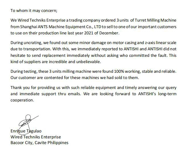
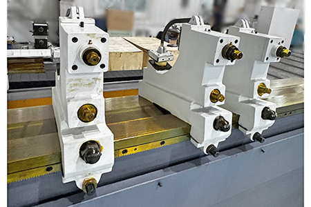
MKZW1363x70 Wheel Head Moving CNC Cylindrical Grinding Machine
Max. grinding outer diameter range: 630mm
No installation required
Simple operation
Support video teaching
1 Year for machinery warranty
On Stock
Email : contact@antsmachine.com
(your request will be responsed within 1 hour.)
Technical Parameter :
Machine limit position dimensions
| Machine size | Length(mm) | Width(mm) | Height(mm) |
| Ø630×7000 | 14500 | 3500 | 2500 |
Main Specifications
| Grinding outer diameter range (mm)
Center height (mm) |
Max. | 630 |
| Mini | 30 | |
| Headstock top taper | 370 | |
| Tailstock top taper | Metric 80# | |
| Top distance (mm) | Metric 80# | |
| Maximum grinding outer diameter length (mm) | 7000 | |
| Maximum grinding length when dressing the grinding wheel with the tailstock dresser (mm) | 7000 | |
| Maximum workpiece weight for top grinding (Kg) | 6750 | |
| Maximum workpiece weight for support grinding (Kg) | 1500 | |
| Grinding outer diameter range (mm) | 3000 | |
| Tailstock top sleeve travel (mm) | 70 | |
Headstock
| Possibility of headstock spindle rotation | Non-rotatable |
| Possibility of headstock body shell rotation | Non-rotatable |
| Headstock dial speed (r/min) | 10~100 |
| Headstock spindle front taper hole | Metric 80# |
Carriage
| Max. longitudinal movement (mm) | 7000 |
Grinding wheel stand
| Horizontal stroke (mm) | 320 | |
| Grinding wheel linear speed (m/s) | ≤35 | |
| Grinding wheel size (mm) | Max. | Ø750×75×Ø305 |
| Wear to | Ø550×75×Ø305 | |
Hydraulic system
| Oil pump flow (L/min) | 25 |
| Main system adjustment pressure (Mpa) | 1.2~1.4 |
| Auxiliary system adjustment pressure (Mpa) | 0.5~0.7 |
| Lubrication system adjustment pressure (Mpa) | 0.4~0.6 |
Cooling system
| Cooling pump rated flow (L/min) | 50 |
Accuracy
| Roundness mm | 0.005 |
| Diameter consistency mm | 0.020/1000 |
| Surface roughness Ra (μm) | 0.4 |
Electrical system
Grinding wheel motor power: 22KW;
Head-stock motor power: 15KW;
Total machine power: 55KW;
HNC CNC system, other systems can also be configured according to user requirements, like FANUC ect
Resources & Downloads:
MKZW1363x70 Wheel Head Moving CNC Cylindrical Grinding Machine Product Introduction :
Main Application
1. This machine tool is suitable for grinding the outer cylindrical surface of slender shaft parts such as lead screws, and is used in various production occasions. The feature of this machine tool is the integrated bed structure with a movable grinding wheel frame.
2. The overall structure of this machine tool adopts a movable grinding wheel frame layout, and the main component structures include: headstock, tailstock, grinding wheel frame, carriage, and horizontal feed mechanism.
3. The longitudinal movement of the grinding wheel frame of this machine tool is achieved by a servo motor driving a high-precision rack through a reduction gearbox; the horizontal feed of the grinding wheel frame is achieved by a servo motor driving a ball screw.
4. The workpiece, grinding wheel, oil pump and cooling pump are driven by independent motors respectively.
Features
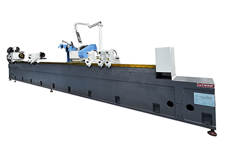
Headstock
1. The headstock of this machine is box-shaped and fixed on the workbench by two M30 bolts. Due to the use of a dead center device, the rigidity is good, which improves the grinding quality.
2. The headstock can rotate the hexagonal head according to actual needs, and move it to the desired position along the workbench longitudinally through the gear rack.
3. The tapered hole in the front of the headstock spindle can be installed with a metric 80# center. The variable frequency motor located on the top of the body shell can change the motor speed through the inverter so that the headstock spindle can obtain a speed of 10 to 100rpm. Therefore, when grinding the workpiece, you can choose the appropriate spindle speed. When the workpiece is small, a higher spindle speed should be selected; when the workpiece is large and heavy, a lower speed should be selected, so that better machine tool grinding accuracy can be obtained.
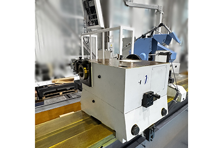
Tailstock
1. The tailstock of this machine is fastened to the right side of the workbench by two M30 bolts. When grinding workpieces of different lengths, the hexagonal head can be rotated and moved to the desired position along the workbench longitudinally through the gear rack.
2. Turn the hand wheel and the sleeve can be moved forward and backward in the body shell through the screw. The metric 80# tip is configured in the tapered hole in the front of the sleeve. A set of disc springs are placed at the rear of the screw to compensate for the thermal expansion caused by grinding the workpiece.
3. There is a dresser on the left side of the tailstock. When dressing the grinding wheel, the dresser can be moved forward and backward as needed. When using the dresser to dress the grinding wheel, the workpiece does not need to be removed, which is convenient for operation. However, in special cases such as when the workpiece is long or the workpiece diameter is large, the dresser installed on the workbench should still be used.
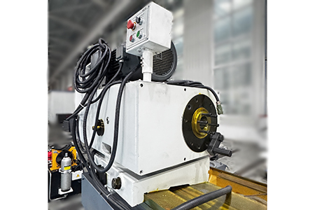
Grinding wheel frame
1. The grinding wheel frame of this machine tool consists of an upper and lower part. Its internal spindle support adopts a dynamic and static pressure bearing structure. The dynamic and static pressure bearing has axial and radial support functions. When the external static pressure lubrication pressure oil is injected, the spindle floats. The AC asynchronous motor drives the spindle to rotate through the belt and pulley to generate a dynamic pressure rigid oil film, thereby supporting the rotation of the spindle.
2. The transverse guide adopts a flat-V structure, and the guide surface is plastic-coated. Its friction coefficient is small, which can more effectively maintain the original accuracy of the guide and improve the life of the guide pair. The transverse guide adopts open throttling static pressure lubrication.
Longitudinal feed
The longitudinal movement of the grinding wheel frame of this machine tool is achieved by the servo motor driving the high-precision gear rack through the reduction box.
Transverse feed mechanism
The transverse feed mechanism of the grinding wheel frame of this machine tool is located on the back of the bed. It is achieved by the servo motor driving the ball screw through the reduction mechanism.
Standard Configuration
| Name | Part No | Specifications | Quantity | Remark |
| Electric box | 1 Set | Installed on machine | ||
| Sediment coolant tank | 50L/min | 1 Set | ||
| Hydraulic station | 1 Set | |||
| Spindle hydraulic station | 1 Set | For grinding wheel head spindle | ||
| Measuring bridge | M1363×50-85-100 | 1 Pcs | ||
| Grinding wheel outer circle dresser | M1363*50-60 | 1 Set | Without diamond pen, installed on the workbench | |
| Open center frame | M1363*50-63 | Support diameter 30~200 | 2 Sets | |
| Open center frame | M1363*50-63/1 | Support diameter 200~350 | 2 Sets | |
| Machine pad iron | 1 Set | |||
| Chuck | MZW1380×80-85-001 | φ300~φ400 | 1 Set | |
| Clamp chuck | M1350×30-85-001 | Ø150~Ø300 | 1 Pcs | |
| M1350×30-85-002 | Ø75~Ø150 | 1 Pcs | ||
| Grinding wheel clamping flange | HJX37-100 | 1 Set | ||
| Top | M1363×50-85-300 | Metric 80# | 2 Pcs | |
| Hexagonal socket wrench | HS92-9 | 75 | 1 Pcs | For disassembling and installing grinding wheels |
| Grinding wheel remover head | HS79-1 | M135×2 | 1 Pcs | For disassembling and installing grinding wheels |
| Grinding wheel hanging rod | HS79-2 | 600 | 1 Pcs | For disassembling and installing grinding wheels |
| Balance shaft | HS79-3 | Ø100(1:5 Taper) | 1 Set | For balancing grinding wheels (including nuts and washers)) |
| Grinding wheel | P750×75×305
WA60K6V35 |
750×75×305 | 1 Pcs |
Note:
1. If there are special requirements for the grinding wheel, the user needs to provide the brand before signing the contract, and it will be confirmed by Party B, and the price needs to be calculated separately.
2.The standard configuration is a simple packaging with wooden bar support, and the wooden base packaging is a special package with PCs, and the price needs to be calculated separately.
Optional Configuration
| Name | Part No | Specifications | Quantity | Remark |
| Grinding wheel balance frame | HJX85-03 | 1Set | ||
| Grinding wheel end face dresser | HJX37-270A | 1Set | Without diamond pen, installed on the workbench | |
| Grinding wheel arc dresser | HJX36-270 | 1Set | Without diamond pen, installed on the workbench | |
| Magnetic separator coolant tank | 50L/min | 1Set | When optional, the standard coolant tank is cancelled | |
| Open center stand | HJX45-270 | Support diameter 25~200 | ||
| Open center stand | M1350×30-63/1 | Support diameter 200~350 | ||
| Closed center stand | HJX11-270 | Support diameter 25~200 | ||
| Outer diameter measuring instrument | Measurement range 25~290 | |||
| End face measuring instrument |
Get The Required Product Quotation As Quickly As Possible
If possible, Given detailed request helps to gain better-matched customized solution. Thanks for your patience. your request will be responsed within 1 hours, kindly pay attention to your email please.
WHAT OUR CLIENTS SAY
Deliver good machines, enjoy good life
In the fall of 2024, I ordered a CNC bandsaw machine from Shanghai ANTS Machine Equipment Co., LTD to be used in our handrail production factory. I can confidently verify the exceptional quality and functionality of this machine. It has proven to be a valuable addition to our production process. The professionalism of their sales, service and support team—especially Baccata—has been superb and greatly appreciated.
Because of my 100% satisfaction with this experience, I have recently purchased a CK6150 CNC Lathe from them and am already looking to purchase more equipment in the near future.
USA Bobby Kelly Purchase manager
We ordered three sets of machines from Shanghai ANTS Machine Equipment Co.,LTD to use for our production in 2021. Two sets of double columns gantry horizontal saw machine and one turret milling machine During testing, the machines were found to have 100% same performance dimensions as our request. These machines are working as expected ever since, without any problems.
Thank you for providing us with such reliable equipment and service support. We are looking forward to ANTISHI’s long-term cooperation.
SLOVAKIA Michal Štromajer Maintainence Manager
To Whom It May Concern,
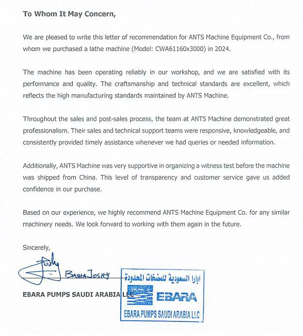
We are pleased to write this letter of recommendation for ANTS Machine Equipment Co., from whom we purchased a lathe machine (Model: CWA61160x3000) in 2024. The machine has been operating reliably in our workshop, and we are satisfied with itsperformance and quality, The craftsmanship and technical standards are excellent, whichreflects the high manufacturing standards maintained by ANTS Machine. Throughout the sales and post-sales process, the team at ANTS Machine demonstrated greatprofessionalism, Their sales and technical support teams were responsive, knowledgeable, and consistently provided timely assistance whenever we had queries or needed information. Additionally, ANTS Machine was very supportive in organizing a witness test before the machinewas shipped from China, This level of transparency and customer service gave us addedconfidence in our purchase. Based on our experience, we highly recommend ANTS Machine Equipment Co. for any similarmachinery needs. We look forward to working with them again in the future.
SAUDI ARABIC Basha Joshy Purchase & Logistics
We are happy to share our positive experience with the CNC lathe purchased from Shanghai ANTS Machine Equipment Co., LTD. In our communication and cooperation process, we found the machine to be outstanding in multiple aspects. First, the appearance of the CNC lathe is very attractive, and everyone in our team likes its look. More importantly, in terms of functionality, our biggest concern was the way to clean out swarf and long chips. This lathe provides good solution by customising sheet metal for us, effectively solving our cleaning problem. The build quality of the machine has left a deep impression on our workers.
We are very satisfied with the performance, quality, and service of this CNC lathe. Based on this pleasant cooperation experience, we highly recommend ANTS Machine Equipment Co., LTD. We look forward to continuing long - term cooperation with ANTS in the future and believe that their equipment and services will bring more value to more customers.
UK Peter Hart General Manager
With this letter we recommend AN'TS Machine Equipment Co., LTD. as a good and reliable manufacturer and supplier of the equipment which is of high quality. In 2024 ANT'S Machine Equipment Co., LTD. supplied the CNC LATHE machine model CK6152E x 1000 for a very short time of produce. All the work was performed with high responsibility and quality. Commissioning was not demands because unpacking, connecting and using was very easy and comfortable. All questions were decided so fast like we are fell that their specialists stay near with you. In future we have a plan to purchase also machine but with another properties and targets.
We are grateful to ANT'S Machine Equipment Co, LTD. for the good job, cooperation and support.
RUSSIA CEO of LLC «POLYTRADE GROUP» Mr. Vitaly Karamyshev
To Whom It May Concern,
In 2023, i ordered a Vertical Machining Center VMC1275, Surace Grinder M7170A and CK6150CNC Lathe to be used in our production factory. I can confidentty verify the exceptional quality and functionality of this machine. it has proven to bea valuable addition to our production process. The professionalism of their sales, service andsupportteam has been supert and greatly appreciated. Because of my 100% satisfaction with this experience, l have recently purchased a Press Brake from them and am already looking to purchase more equipment in the near future.
Phillipines Raymond Estrada Maintenance Manager
To whomsoever it may concern;
In December 2021, we ordered one set Shaping machine from Shanghai ANTS Machine Equipment Co.,LTD to install in a newly build Georgian State Maritime academy, the machine should be used for a training purpose for marine mechanic students. During the testing, after proper installation of the machine performance was 100% in compliance with the requirements. Machine has a 1-year warranty, until now it shows high performance and we are satisfied with the purchase. Thank you for providing us with such reliable equipment and service support. We are looking forward to ANTISHI's long-term cooperation.
Georgia Konstantine Tskhvaradze Purchase manager

BelarusBasalai Aliaksandr Viktorovich Indiv idual Entrepreneur
Saudi Arabia EBARA PUMPS SAUDI ARABIA LLC
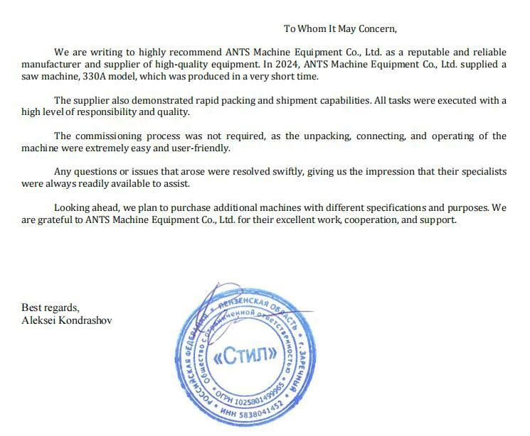
Russia Aleksei Kondrashov - ООО "СТИЛ"