


The slant bed CNC lathe, with the innovative design of the C-axis and Y-axis, has played a crucial role in the field of machining, opening up a new situation for high-efficiency and precision machining.
Functions of the Y-axis in Slant Bed CNC Lathes
Expanding the Machining Space Dimension
The Y-axis in an slant bed CNC lathe breaks through the limitation of traditional lathes that only move along the X (transverse) and Z (longitudinal) axes. The Y-axis is perpendicular to the spindle direction, enabling the tool to move horizontally left and right, expanding the machining space from two dimensions to three dimensions. This means that it can machine part structures such as eccentric features, irregular contours, and complex hole systems that are beyond the scope of traditional lathe machining, greatly enriching the types of machinable parts.
Improving Machining Accuracy and Efficiency
When machining complex parts, ordinary lathes often require multiple clamping operations to complete the machining of different parts, which is prone to cumulative errors. The slant bed CNC lathe with a Y-axis can achieve multi-process machining in one clamping through multi-axis linkage. For example, when machining eccentric holes, the Y-axis, in coordination with the X and Z axes, accurately positions the tool, reduces the number of clamping operations, ensures the positional accuracy of the holes, and at the same time shortens the machining time and improves production efficiency.
Enhancing Machining Flexibility
The Y-axis enables the lathe to perform a variety of machining operations. In addition to turning, it can also perform milling and drilling. For example, when machining parts with planes and grooves, after turning, the Y-axis can drive the milling cutter to perform groove milling operations without the need to change the equipment. Multiple processes can be completed on one lathe, meeting diverse machining requirements.
Functions of the C-axis in Slant Bed CNC Lathes
Achieving Circular Indexing and Positioning: The C-axis is essentially an axis of rotation around the axis of the lathe spindle. It can accurately control the position of the workpiece or tool in the circumferential direction. When machining some parts that require circumferentially evenly distributed features, such as the sprocket on an engine, the teeth on the sprocket need to be evenly distributed on the circumference. With the help of the C-axis, the lathe can accurately rotate the workpiece to the specified angle, and then cooperate with the tool for milling or turning, ensuring the indexing accuracy of the teeth. The error can be controlled within a very small range, usually up to ±0.001°, greatly improving the machining accuracy in the circumferential direction of the part.
Expanding Turning Functions: The C-axis, in coordination with the X and Z axes, can achieve the machining of complex revolving parts such as turning spiral grooves and threads. When machining multi-start threads, the C-axis controls the rotation angle of the workpiece, and the X and Z axes control the feed of the tool. Through the precise cooperation of the three, high-precision threads with different pitches and different starts can be machined, meeting the processing requirements of parts such as hydraulic pump screws. Compared with traditional single-axis thread turning, the efficiency is significantly improved, and at the same time, the machining accuracy is higher, and the surface roughness of the thread is lower.
Cooperating with Milling Machining: When performing milling operations, the C-axis can drive the workpiece to rotate, allowing the tool to mill the workpiece from different angles. For example, when machining some parts with complex curved surfaces, such as impellers, the C-axis, in coordination with the Y-axis and the milling cutter, can achieve the precise milling of the impeller blade surfaces, making the tool path more flexible and diverse, and enabling the machining of complex curved surfaces that are closer to the design requirements, improving the hydraulic and mechanical properties of the impeller.
Collaborative Effects of the C-axis and Y-axis
Machining Complex Irregular Parts: For some irregular parts in the aerospace field, such as the engine casing of an aircraft, there are numerous irregular bosses, holes, and grooves on its surface, distributed at different angles and positions. The C-axis and Y-axis work together. The C-axis rotates the workpiece to the appropriate angle, and the Y-axis controls the horizontal movement of the tool. In coordination with the X and Z axes, the machining of these complex features can be completed in one clamping. The tool can move along a complex spatial curve trajectory to accurately remove materials, achieving high-precision machining of irregular parts, greatly reducing the number of part clamping operations, reducing cumulative errors, and improving the overall machining accuracy and production efficiency of the parts.
Realizing Composite Machining Processes: In the manufacturing of automotive parts, such as machining automotive half shafts, traditional processing processes require multiple pieces of equipment to perform turning, milling, drilling, and other operations respectively. However, for the slant bed CNC lathe with a C-axis and a Y-axis, the C-axis controls the rotation of the half shaft, and the Y-axis drives the tool for milling or drilling. When machining the splines on the half shaft, the C-axis rotates the workpiece, and the Y-axis, in coordination with the milling cutter, mills along the spline contour. At the same time, combined with the movement of the X and Z axes, multiple processes such as outer circle turning, spline milling, and end drilling of the half shaft can be completed in one clamping, truly realizing composite machining, shortening the process flow, and improving production efficiency and product quality.
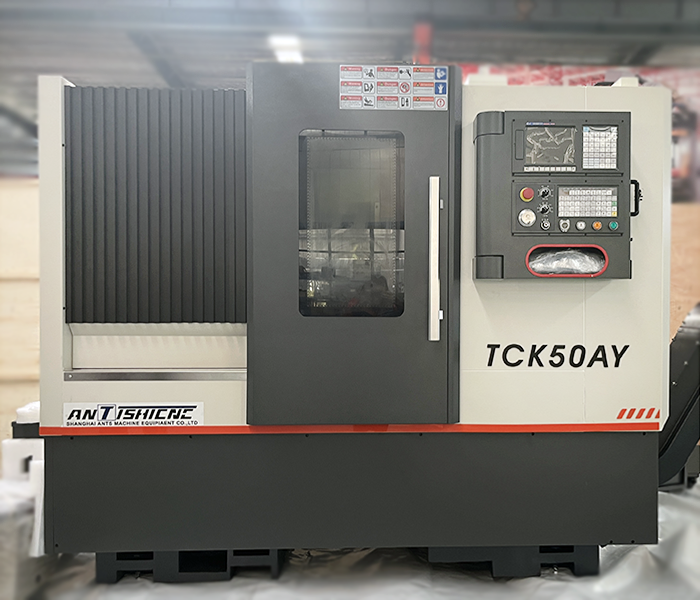
Shanghai ANTISHICNC Slant Bed CNC Lathe TCK50AY*800 (with Y-axis & C-axis)
Features of TCK50AY*800:
The overall machine has a compact structure and an aesthetic appearance. It has stable and reliable performance and excellent accuracy retention. The 30° integral slant bed structure is equipped with high-precision pre-loaded Taiwan linear roller guides, ensuring positional accuracy and facilitating high-speed and high-precision machining and chip removal. The high-precision spindle has been precisely assembled and dynamically balanced, with low noise and high rigidity. The turret has a fast tool change speed and high positioning accuracy. The X and Z directions are directly connected to the lead screw by servo motors, ensuring positioning accuracy. The advanced centralized automatic lubrication device works stably. The machine is equipped with a domestic hydraulic chuck, and the hydraulic tailstock adopts a processing method of manual adjustment and locking and hydraulic piston tightening of the workpiece.
Technical Parameters of TCK50AY*800:
| Item | Unit | TCK50AY-800 | |
| Max swing dia. over bed | mm | Φ640 | |
| Max swing dia. over slide | mm | Φ380 | |
| Center distance | mm | 800 | |
| Max disc processing diameter | mm | Φ450(When adjacent tools do not interfere) | |
| Max turning length | mm | 700 | |
| Spindle end type | – | A2-8 | |
| Spindle through hole diameter | mm | Φ86 | |
| Bar diameter | mm | Φ75 | |
| Hydraulic chuck | mm | 10 inch | |
| Hydraulic chuck tie rod through hole | mm | Φ75 | |
| Guide type | – | Linear guideways | |
| Spindle taper | – | Metric 92 1:20 | |
| Spindle speed | rpm | 3000rpm | |
| Tailstock sleeve diameter | mm | 90 | |
| Tailstock sleeve inner hole taper | No | MT5 | |
| Tailstock sleeve stroke | mm | 80 | |
| Tailstock type | – | Hydraulic (programmed) | |
| Tailstock stroke | mm | 700 | |
| Power turret | set | 12 | |
| Tool holder model | BMT45 | ||
| Y-axis stroke | mm | ±45 | |
| Power turret chuck | mm | (ER25) | |
| Tool holder size | mm | 25´25 | |
| Max boring tool diameter | mm | Æ32 | |
| Screw model | X direction | 3210 | |
| Z direction | 4010 | ||
| Guide model | X direction | RGH45CA2R725 | |
| Z direction | RGH45CA2R1515 | ||
| X/Z motor torque | N.M | 15/15 | |
| X/Z fast moving speed | m/min | 18/18 | |
| X stroke | mm | 260 | |
| Z stroke | mm | 800 | |
| Min setting unit | mm | 0.001 | |
| Main motor power | KW | 15 | |
| Total power | KW | 32 | |
| Machine tool net weight | Kg | 4000 | |
| Overall dimensions (length × width × height) | mm | 3300*2000*2100 | |
The TCK50AY*800 slant bed CNC lathe by Shanghai ANTISHICNC, with its advanced C – axis and Y – axis technology and excellent structural design, is bound to shine in industries such as automotive manufacturing, aerospace, and precision mold, propelling the manufacturing industry to new heights.
If you are in need of a slant bed CNC lathe for high – precision machining, you are welcome to consult Shanghai ANTISHICNC. We have rich experience in the manufacturing and application of CNC lathes and can provide you with professional technical support.