


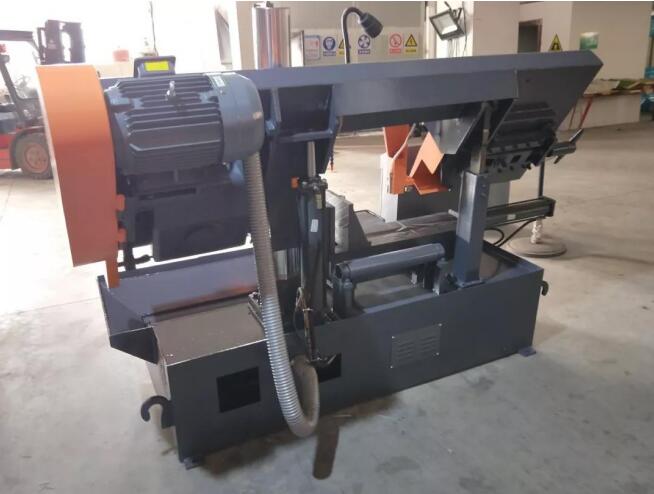
Band sawing machine is a kind of sawing equipment that uses metal saw blades as cutting tools and is used to cut metal materials. It is mainly used for cutting ferrous metal square materials, garden materials and various profiles. It can also be used for cutting non-ferrous metals and non-metal materials. Because the band saw has a narrow cut and high cutting efficiency, it consumes less energy and wastes less material. It is a high-efficiency cutting equipment with significant energy saving and material saving effects.
The main drive of this machine tool adopts worm gear box variable speed. The feed adopts hydraulic transmission, and the workpiece clamping adopts manual and hydraulic hybrid clamping. It has the advantages of compact structure, convenient operation and maintenance, etc.
Overview of the main mechanical structure of the machine tool
1. Machine bed and workbench: The machine bed adopts a welded box structure, which is mainly used to support other parts. The inner cavity has a hydraulic pool and a cooling liquid pool. The workbench is a casting and is used for receiving materials, installing clamping devices and saw frames. .
2. Main transmission device: The main transmission adopts worm gear transmission mode, which is composed of motor, belt pulley, worm gear transmission, saw wheel box and saw wheel. It is mainly used to transmit torque and drive the band saw wheel to rotate in order to achieve cutting motion. By changing the belt position on the pulley, the speed can be changed.
3. Saw band tensioning mechanism: It is composed of a driven gear, a sliding seat, a sliding block, a screw rod, and a nut. The band saw blade can be tensioned by moving the driven wheel to ensure a certain formation between the band saw blade and the rim of the saw wheel. The pressure generated enough friction force to drive the saw blade to rotate and realize the cutting motion. The magnitude of the tension force can be determined by the force measuring wrench.
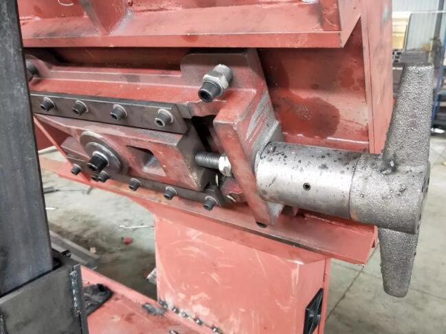
4. Working clamping mechanism: working clamping adopts a mixed method of hydraulic and manual clamping. Manual clamping is through the handwheel screw nut and rack and pinion, so that the clamp can move to achieve the purpose of clamping and loosening. Hydraulic clamping is controlled by hydraulic cylinders and manual valves to achieve clamping and unclamping.
5. Saw band guide: It is composed of left and right guide arms and guide heads. The guide head is composed of guide rollers and guide blocks. It is mainly used to twist the band saw blade to a certain angle so that it is perpendicular to the table surface to ensure the correct position of the saw blade. Improve cutting accuracy.
6. Cooling system: It is composed of a coolant tank, a cooling pump, a pipe, a valve and a nozzle, which is used to ensure the supply of sufficient coolant to the cutting area to improve the cutting effect, the service life of the saw band and the accuracy of the cutting section. For removing chips from the teeth.
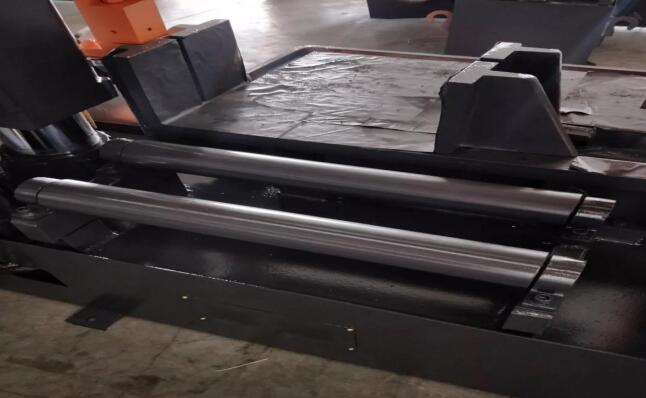
7. Material bearing frame: It is composed of rollers, brackets and material holders to support longer workpieces and make them parallel to the workpiece table to ensure normal cutting.
The hydraulic drive system of the machine tool
Overview of the hydraulic system of the machine tool: This system is composed of the machine pool (inner cavity of the machine bed), the motor, the pump station, the oil pipe and the executive element-the oil cylinder and the control system, which are used to realize the supply of the saw frame, the lifting and the clamping of the workpiece ( Hydraulic clamping type), the feed speed can be adjusted steplessly through the speed control valve to ensure the normal cutting of workpieces of different materials.
Three, machine tool electrical control system
1. The electrical system is composed of an electrical box, a control box and a travel switch. It is used to control a part of the machine tool’s actuators (cylinders), so that they can operate in an orderly manner according to a certain working procedure to achieve a normal cutting cycle. Implement protection to avoid equipment accidents.
2. Electrical control instructions: All operating buttons of electrical control components are concentrated on the operation panel except for the travel switch and solenoid valve. During operation, you only need to press the corresponding function button according to a certain procedure to perform normal work. Each button All have corresponding function indication signs. When the machine is stopped, press the button with the red mushroom head to realize the total stop. The raised height of the saw frame can be adjusted by the stroke switch lever fixed on the end of the saw frame’s rotary shaft, so as to achieve the required height. The lower limit stroke of the saw frame is controlled by a limit switch installed at the left end of the workbench.