


1. Tool Exchange Function for CNC Lathe Machines
1.1 Tool Exchange
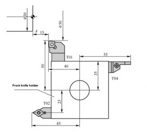
Command format 1: T0101; this command is the tool rotation command of the FANUC system, the front T01 means changing the No. 1 tool, and the latter 01 means using the No. 1 tool compensation. The tool number and the tool compensation number can be the same or different.
Command format 2: T04D01; this command is a tool rotation command of the SIEMENS system, T04 means changing the No. 4 tool, D01 means using the No. 1 cutting edge of the No. 4 tool as the tool compensation memory.
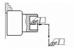
1.2 Tool change point
The so-called tool change point refers to the position when the tool post is automatically indexed. For most CNC lathes, the position of the tool change point is arbitrary, and the tool change point should be selected at a position that does not interfere with the workpiece or fixture during the tool exchange process. The position of the tool change point of some machine tools is a fixed point. Usually, these points are selected near the reference point of the machine tool, or the second reference point of the machine tool is taken as the tool change point.
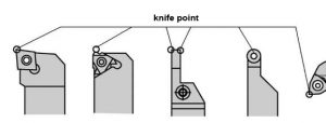
2. Tool Compensation and Tool Position Points
The so-called tool position point refers to the point used to represent the tool characteristics during programming and processing, and is also the reference point for tool setting and processing. The tool position of the CNC turning tool is shown in the figure. The tool point of the pointed turning tool usually refers to the tool tip; the tool point of the arc-shaped turning tool is the center of the arc edge; the tool point of the forming tool also usually refers to the tool tip.
3 Tool offset compensation
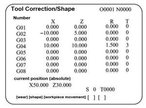
3.1 Meaning of tool offset
Tool offset is a function to compensate for the difference between the assumed tool length and the reference tool length. The CNC system of the lathe stipulates that the X axis and the Z axis can realize the tool offset at the same time.
Tool Geometry Offset: Tool offset due to different tool geometry and different tool mounting positions.
Tool Wear Offset: Tool offset caused by wear on the tool tip.
3.2 Tool setting operation using tool geometry offset
(1) Definition of tool setting operation
Adjusting the knife position of each knife to make it coincide with an ideal reference point as much as possible is called knife setting.
(2) The process of tool setting operation
① Manually operate the machining end face, and record the Z-direction mechanical coordinate value of the tool position point.
② Manually process the outer circle, record the X-direction mechanical coordinate value of the tool position, stop the machine to measure the diameter of the workpiece, and calculate the mechanical coordinate value of the spindle center.
③ Input the X and Z values into the corresponding tool geometry offset memory.
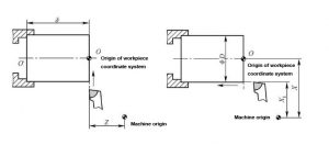
(3) The essence of tool setting operation using tool geometric offset
The essence of tool setting using tool geometric offset is to use tool geometric offset to make the origin of workpiece coordinate system coincide with the origin of machine tool.
3.3 Application of tool offset
The tool offset function can be used to correct workpiece machining errors caused by incorrect tool setting or tool wear. For example: when machining the outer surface, if the diameter of the outer circle is 0.2mm larger than the required size, just reduce the X value in the tool offset memory by 0.2, and re-machine the part with the original tool and the original program, that is, This machining error can be trimmed. Similarly, if there is an error in the Z direction, the trimming method is the same.