


Threads are one of the common geometric features in mechanical engineering and are widely used. Thread processing technology is more, such as based on plastic deformation of rolling and thread rolling, based on the cutting process of turning, milling, tapping threads and sets of threads, thread grinding, thread grinding and so on.
1.Types of threads
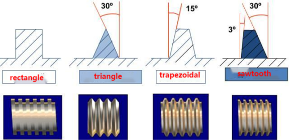
According to the tooth type can be divided into triangular, trapezoidal, rectangular, serrated and arc thread;
According to the direction of thread rotation can be divided into left-handed and right-handed;
According to the number of spiral line can be divided into single line and multi-line;
According to the shape of the thread body is divided into cylindrical and conical and so on.
| Type | Code name | Picture | Application | ||
| Coupling thread | Common thread | coarse | M |  |
The most commonly used coupling thread |
| Fine | For fine precision or thin-walled parts | ||||
| Pipe thread | G |  |
Used on thin-walled pipes such as water pipes, oil pipes, gas pipes, etc. for pipeline coupling. | ||
| Drive thread | Trapezoidal thread | Tr | 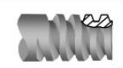 |
Used for various machine tool screws for transmission. | |
| Serrated thread | B | 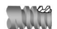 |
Only unidirectional power can be transmitted. | ||
2.Elements of a thread
Thread includes five elements: tooth type, nominal diameter, number of threads, pitch (or lead), and direction of rotation.
| Tooth type | The shape of the thread profile in the profile area through the thread axis is called the tooth pattern. There are triangular, trapezoidal, serrated, circular and rectangular shapes. | Comparison of the thread’s tooth type:
|
| Diameter | Threads have a large diameter (d, D), medium diameter (d2, D2), small diameter (d1, D1), in the representation of the thread is used in the nominal diameter, the nominal diameter is representative of the diameter of the thread size.
The nominal diameter of a common thread is the large diameter. |
External thread Internal thread |
| Thread count | Threads formed along a helix are called single threads, and threads formed by two or more helixes distributed at equal distances along the axial direction are called multi-threads. | 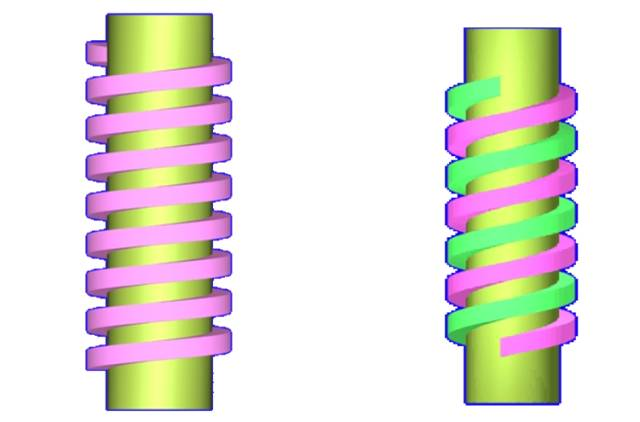
Single thread Double thread |
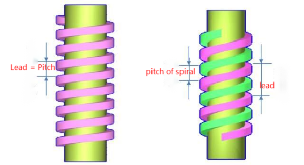
| Pitch and lead | Pitch (p) is the axial distance between two adjacent teeth at two corresponding points on the centre diameter line. Pitch (ph) is the axial distance between two adjacent threads on the same helix at two corresponding points on the centre diameter line.
In the case of single thread, lead = pitch; in the case of multi-thread, lead = pitch x number of threads. |
 |
| Direction of rotation | Threads that are screwed in when rotated clockwise are called right-hand threads;
Threads screwed in counterclockwise are called left-hand threads. |
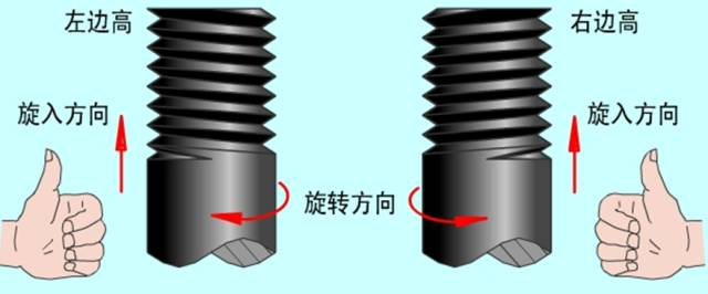
Left-hand thread Right-hand thread |
3. Threading
The method of processing all kinds of internal and external threads with thread machining tools.
Thread cutting
Generally speaking, it refers to the method of processing threads with forming tools or abrasives on the workpiece, mainly including turning, milling, tapping and grinding, grinding and cyclone cutting. Turning, milling and grinding threads, the workpiece every turn, the machine tool transmission chain to ensure that the turning tool, milling cutter or grinding wheel along the axial direction of the workpiece accurately and uniformly move a guide. In tapping or threading, the tool (tap or thread) and the workpiece make relative rotational movements, and the thread groove formed first guides the tool (or workpiece) to move axially.
| 1. Thread turning |
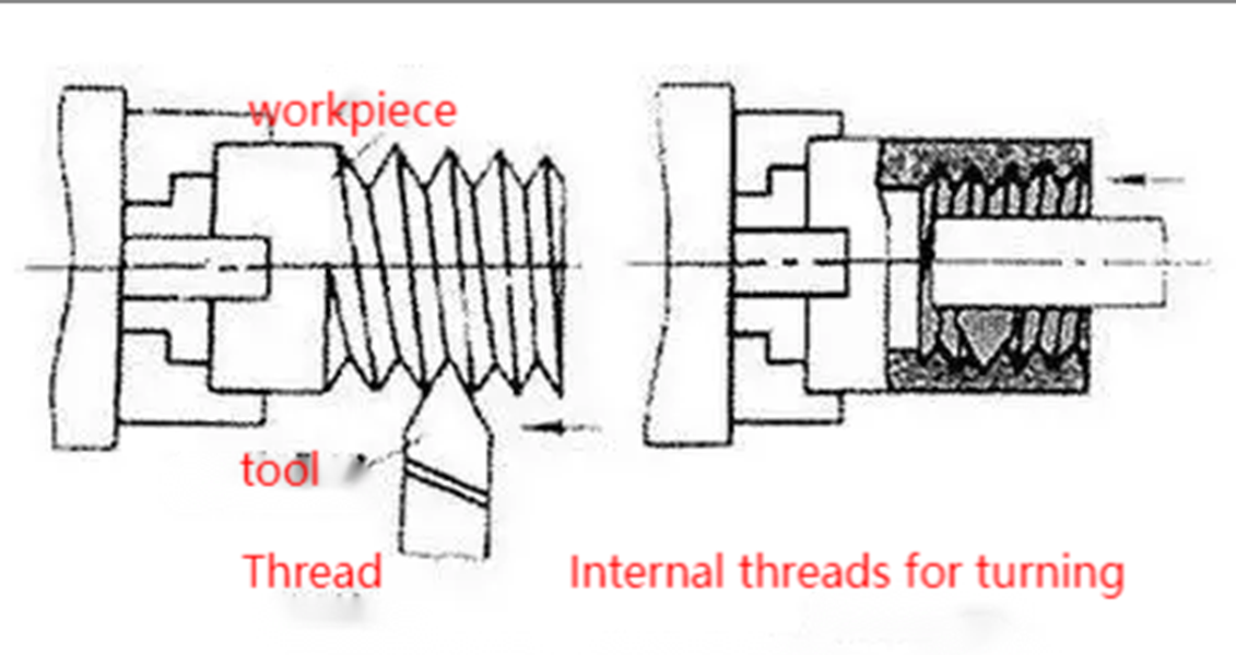 |
| Turning threads on a lathe can be done with either a form turning tool or a thread comb (see Threading Tools). Turning threads with forming cutter is a common method for single piece and small batch production of threaded workpieces due to simple tool structure; turning threads with thread comb cutter has high productivity, but the tool structure is complicated and is only suitable for turning short threaded workpieces with fine threads in medium and large batch production. Ordinary lathe turning trapezoidal thread pitch accuracy generally can only reach 8 ~ 9 level (JB2886-81, the same below); in the specialised thread lathe processing thread, productivity or accuracy can be significantly improved. |
| 2. Thread milling |
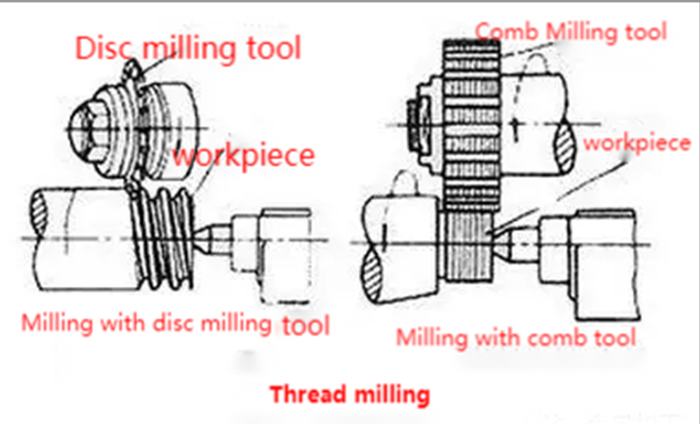 |
| Milling is carried out on thread milling machines with disc milling cutters or comb milling cutters. The disc milling cutter is mainly used for milling trapezoidal external threads on workpieces such as screws and worm gears. Comb milling cutter is used for milling internal and external common threads and taper threads, because it is milling with multi-flute milling cutter, the length of its working part is greater than the length of the processed threads, so the workpiece only needs to be rotated 1.25 ~ 1.5 turns can be processed to complete the workpiece, and the productivity is very high. The pitch accuracy of thread milling can generally reach 8~9 levels, and the surface roughness is R5~0.63 microns. This method is suitable for batch production of threaded workpieces of general accuracy or roughing before grinding. |
| 3. Thread grinding |
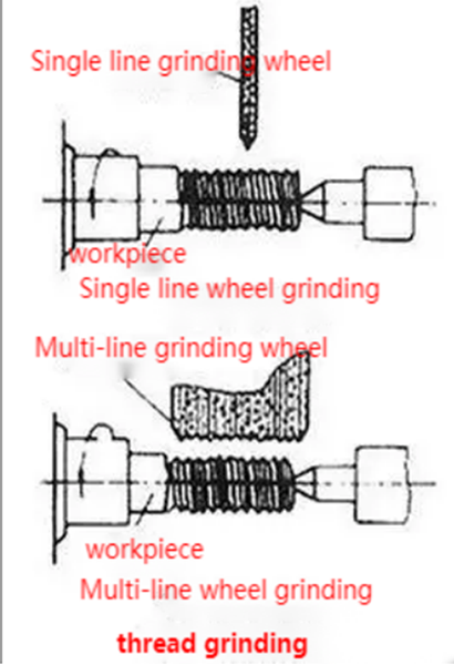 |
| It is mainly used for processing precision threads of hardened workpieces on thread grinding machines, and is divided into two kinds of grinding wheels according to the different cross-sectional shapes of the grinding wheels, namely, single-line grinding wheel and multi-line grinding wheel. The pitch accuracy achieved by single line grinding is 5~6, the surface roughness is R1.25~0.08 micron, and it is convenient to dress the grinding wheel. This method is suitable for grinding precision screws, thread gauges, worm gears, small batches of threaded workpieces and grinding precision hobs. Multi-line grinding wheel grinding is divided into longitudinal grinding method and plunge-cut grinding method. The width of the grinding wheel of the longitudinal grinding method is less than the length of the thread to be ground, and the grinding wheel can be moved longitudinally for one or several strokes to grind the thread to the final size. The width of the grinding wheel of the plunge-cut grinding method is greater than the length of the thread to be ground, the grinding wheel radially cuts into the surface of the workpiece, and the workpiece can be ground by turning about 1.25 revolutions, which has higher productivity, but with slightly lower precision and more complicated dressing of the grinding wheel. The plunge-cut grinding method is suitable for grinding a larger batch of taps and grinding some threads for fastening. |
| 4. Thread grinding |
 |
| A nut-type or screw-type thread grinding tool is made from softer materials such as cast iron, and the threads that have been processed on the workpiece are rotated forward and backward on the part where the pitch error exists, in order to improve the pitch accuracy. Hardened internal threads are also usually ground to eliminate deformation and improve accuracy. |
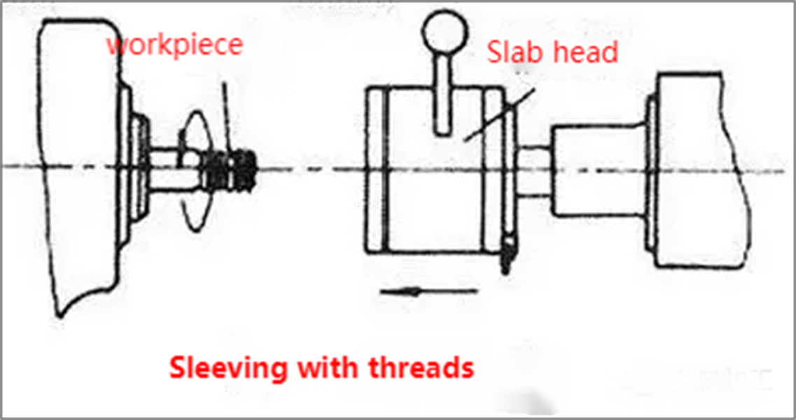
| 5. Tapping and socketing |
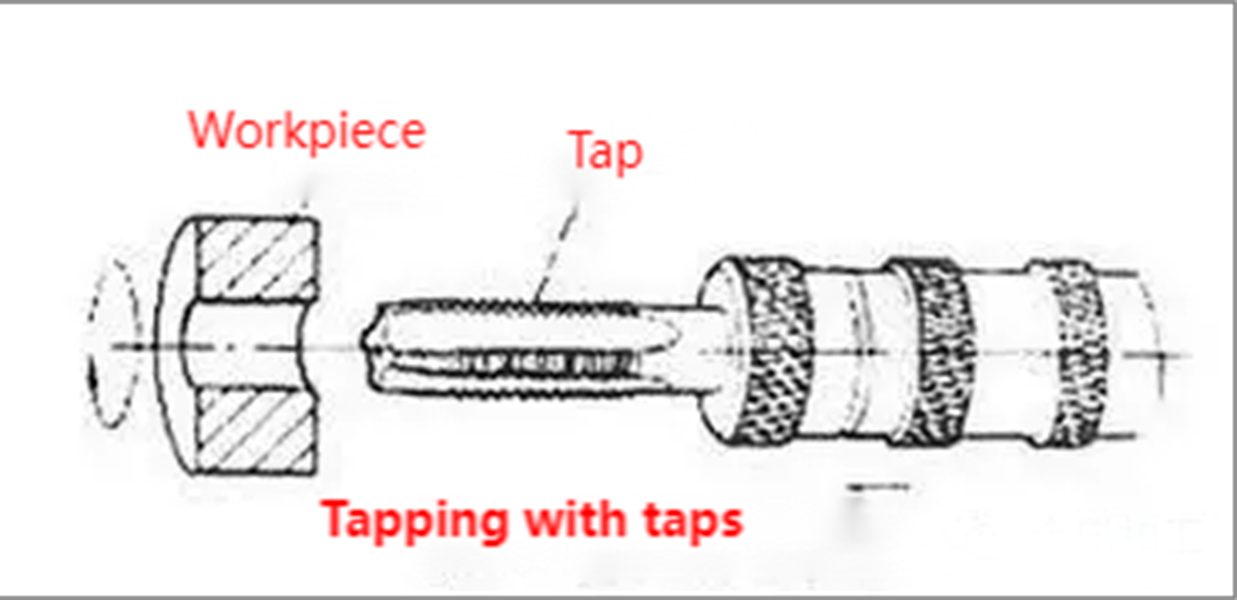  |
| Tapping is the use of a certain torque tap screwed into the workpiece pre-drilled holes in the bottom of the processing of internal threads.
Sleeving is to use the plate teeth in the bar (or pipe) workpiece to cut out the external thread. The accuracy of tapping or threading depends on the accuracy of the tap or plate. Although there are many ways to process internal and external threads, the small diameter of the internal thread can only rely on tap processing. Tapping and socketing can be done manually or with lathes, drilling machines, tapping machines and socketing machines. |
Thread rolling
Forming rolling moulds to make the workpiece to produce plastic deformation to obtain the thread processing method thread rolling generally in the thread rolling machine thread rolling machine or in the attachment of automatic opening and closing thread rolling head of the automatic lathe for mass production of standard fasteners and other threaded couplings of the external threads. Rolling thread outside diameter is generally not more than 25 mm, length is not more than 100 mm, thread accuracy up to level 2 (GB197-63), the diameter of the blank used is roughly equal to the centre diameter of the thread being processed. Rolling generally can not process the internal thread, but for the softer material of the workpiece can be used without groove extrusion tap cold extrusion of internal thread (maximum diameter of up to 30 mm or so), the principle of work is similar to tapping. Cold extrusion of internal threads when the required torque is about 1 times larger than tapping, machining accuracy and surface quality is slightly higher than tapping.
| Thread rolling | |
| Advantage | ① The surface roughness is less than turning, milling and grinding;
②The thread surface after rolling can improve strength and hardness due to cold work hardening; ③ high material utilisation; ④ productivity than the cutting process has increased exponentially, and easy to automate; ⑤ Rolling mould life is very long. However, the hardness of the workpiece material required for rolling threads does not exceed HRC40; the dimensional accuracy of the blank requires high accuracy; the accuracy and hardness of the rolling mould also requires high accuracy and hardness, and the manufacture of moulds is more difficult; it is not suitable for rolling threads with asymmetric tooth shapes. |
| Classification | Thread rolling
Two thread rolling plates with threaded teeth are staggered 1/2 pitch relative to each other, the static plate is fixed, and the dynamic plate makes reciprocating linear motion parallel to the static plate. When the workpiece is fed between the two plates, the movable plate advances and rolls the workpiece to make its surface plastic deformation into a thread. |
| Wire Rolling
Wire rolling has radial rolling, tangential rolling and rolling head rolling 3 kinds of wire. ①Radial wire rolling: 2 (or 3) with a threaded wheel installed in parallel with each other on the shaft, the workpiece is placed on the support between the two wheels, the two wheels in the same direction at the same speed of rotation, which is also a round of radial feed movement. The workpiece is rotated under the roller, and the surface is extruded radially to form a thread. For some of the precision requirements are not high screw, can also be used in a similar way roll forming. ② Tangential thread rolling: also known as planetary thread rolling, the rolling tool consists of a rotating central roller and three fixed arc-shaped silk plate. When rolling, the workpiece can be fed continuously, so the productivity is higher than rolling and radial rolling. ③ Rolling head thread rolling: carried out on automatic lathes, generally used for processing short threads on the workpiece. Rolling head has 3 to 4 rolling wheels evenly distributed around the periphery of the workpiece. When thread rolling, the workpiece rotates and the rolling head feeds axially to roll the workpiece out of the thread. |
|
Thread machining common problems and solutions
| Issue | Reason | Solution |
| Built-up edge | 1)Medium to low cutting speeds 2)Machining of low carbon steel or stainless steel materials |
1) Continue to reduce or increase the cutting speed 2) Mild steel can be tempered, choose good toughness of the inserts, PVD coated inserts are better |
| Excessive wear on the back face | 1)Cutting speed is too high 2)Transverse feed cutting depth is too shallow 3)The tip of the tool is located too much above the centre line of the workpiece. |
1)Reduce cutting speed 2)Reduce the number of feeds 3)Adjust the loading height |
| Uneven wear of left and right cutting edges | 1) The blade inclination angle and the helix angle of the threads Inconsistency 2)Incorrect lateral feed method. |
1)Replacement of suitable knife pads to obtain the correct edge inclination angle 2)Adopt an improved lateral feed method |
| Chipped and broken | 1)Cutting speed is too slow 2)Cutting force is too large 3)Poor chip control and tangling 4)Large deviation of tool tip installation height |
1)Increase cutting speed 2) Increase the number of feeds and reduce the maximum feed volume. 3) Choose the appropriate feed method, increase the pressure of cutting fluid, blowing the chips away 4)Adjust the tool mounting height |
| Tool Plastic Deformation | 1)Cutting speed is too high, cutting temperature is too high 2)Inadequate supply of cutting fluid |
1)Reduce the cutting speed 2) Increase the cutting fluid supply and align the machining area for cooling |
| Poor thread surface quality | 1)Cutting speed is too low 2)Tool tip is above centre height 3)Poor chip control |
1)Increase cutting speed 2)Adjust the tool centre height 3)Change the appropriate tool feed method |
| Incorrect thread profile (Threads too flat) |
1)Tool mounting centre height error is too large 2)Tool wear or breakage |
1)Adjust the tool but mounting height 2)Replace the tool or convert the cutting edge |
| vibratory | 1)Incorrect clamping of the workpiece or cutting tool 2)Improper selection of cutting parameters 3)Tool mounting height error is large |
1)Adjust the clamping status of the workpiece or cutting tool 2)Adjust the cutting parameters. Such as increase or decrease Cutting speed, the use of constant depth of cut into the tool processing 3) Adjust the installation height of the tool |
If you have a need for thread machining, please feel free to consult Shanghai ANTISHICNC. We have rich experience in manufacturing and applying, and can provide professional technical support for you.
Keywords: Thread machining, Mill-turn complex machine, Lathe