


In the field of machining, CNC lathes are indispensable “precision hands,” used for everything from small mobile phone parts and watch gears to large automotive shafts and aerospace components. Many people know that they can precisely machine workpieces, but they are unclear about their internal structure, working principles, and the differences between different types of CNC lathes. Today, we will take a professional perspective and combine practical applications to deeply break down the core knowledge of CNC lathes, from basic components to practical applications, making it easy for beginners to understand.
I. Understanding First: What Exactly is a CNC Lathe?
Simply put, a CNC lathe is an automated lathe controlled by a computer program (CNC system). Its core function is to perform rotary cutting of materials such as metals and plastics, processing raw parts into precision parts that meet design requirements. Unlike traditional lathes, it eliminates the need for manual operation of tool feed and workpiece rotation. Only a pre-programmed machining program is required, and the machine tool can automatically complete a series of processes such as turning, drilling, boring, and threading, resulting in higher precision, faster efficiency, and reduced human error.
Key Advantages: High degree of automation, high machining accuracy, high production efficiency, and wide applicability. It can process simple cylindrical and conical parts as well as complex curved surfaces and threaded parts, making it a “mainstay” of modern manufacturing.
II. In-Depth Breakdown: The Core Components of a CNC Lathe (with Detailed Functional Explanation)
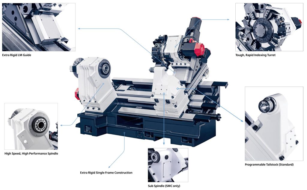
The precise operation of a CNC lathe relies on the coordinated work of its various components. Like the “internal organs” of the human body, each component plays an irreplaceable role. Based on mainstream configurations in actual production, we have broken down the core components in detail, balancing professionalism and ease of understanding:
(I) Bed – The Machine Tool’s “Solid Base”
The bed is the basic skeleton of a CNC lathe. All core components of the entire machine tool (spindle box, tailstock, guideways, etc.) are directly or indirectly mounted on the bed, much like the “skeleton” of the human body, determining the machine tool’s stability and machining accuracy.
Key Features: The bed needs to possess extremely high rigidity, shock resistance, and resistance to thermal deformation; otherwise, vibrations and temperature changes during machining will affect the machining accuracy of the parts. Currently, mainstream manufacturers (such as ANISHICNC) use high-quality Meehanite cast iron to manufacture the bed. This material has a uniform texture and good toughness, effectively reducing thermal deformation, ensuring long-term stable operation of the machine tool, and extending its service life.
Supplementary Knowledge Points: The structural design of the bed is also crucial. Common types include flatbed and slant bed (explained in detail later). Different structures are suitable for different machining scenarios.
(II) Spindle – The “Core Heart” of the Machine Tool
The spindle, often called the “heart” of a CNC lathe, is the core component that drives the workpiece rotation, directly determining the machining speed, accuracy, and stability. It consists of a spindle assembly (spindle body, bearings, etc.) and a spindle drive system (motor, gears, etc.), and is often paired with a chuck and C-axis drive unit.
Core Functions:
• Workpiece Rotation: The spindle rotates at high speed, providing power for cutting, by clamping the workpiece in the chuck.
• Speed Control: The spindle speed is adjusted according to the material being processed (e.g., steel, aluminum, copper) and the machining process (roughing, finishing). The speed range is typically from tens of revolutions per minute to several thousand revolutions per minute, with some high-precision models reaching tens of thousands of revolutions per minute.
• C-Axis Function: With a C-axis drive unit, precise workpiece positioning is achieved, enabling the machining of complex threads, curved surfaces, and even milling (requires appropriate cutting tools).
Additional Highlights: High-quality machine tools (such as ANTS) manufacture their own spindles and components, enabling precise control of spindle vibration levels and reducing machining errors. They can also be configured with spindles of different speeds and power levels to suit various machining scenarios.
(III) Sub-spindle/Second Spindle – A “Good Helper” for Efficiency Improvement
The sub-spindle is an optional configuration, acting as an “auxiliary partner” to the spindle. Independent of the spindle, it can operate synchronously with it, primarily used to achieve “one-time clamping, two-sided machining.”
Core Advantages: Traditional lathe machining requires machining one end of a workpiece, then disassembling and re-clamping it to machine the other end. This is not only time-consuming but also prone to clamping errors. The sub-spindle, however, can prepare for machining the other end while the spindle is machining one end. After the spindle finishes machining, the sub-spindle directly takes over the workpiece and continues machining, significantly improving machining efficiency and reducing clamping errors. It is especially suitable for batch machining of shaft parts.
Note: The machining capacity and power of the sub-spindle are usually consistent with the spindle to ensure uniform machining accuracy at both ends.
(IV) Chuck – A Secure Grip for the Workpiece The chuck is a clamping component mounted on the spindle, similar to a vise. Its core function is to firmly clamp the workpiece to be processed, ensuring that it does not loosen or shift during high-speed rotation, which is one of the keys to ensuring machining accuracy.
Common Types: Based on the clamping method and workpiece type, chucks are mainly divided into three-jaw chucks, four-jaw chucks, hydraulic chucks, and pneumatic chucks:
• Three-jaw chuck: Automatically centers, suitable for clamping regular workpieces such as round and hexagonal shapes; simple to operate and highly efficient.
• Four-jaw chuck: Each jaw can be adjusted individually; suitable for clamping irregularly shaped workpieces; high clamping accuracy.
• Hydraulic/pneumatic chuck: Automated clamping, suitable for mass production, reducing manual operation, and providing uniform clamping force.
Supplement: For extra-long workpieces (such as oil pipes and long shafts), the chuck needs to be used with a tailstock to ensure stable clamping and prevent shaking during machining.
(V) Guide Rails – The “Precision Track” for the Tool
The guide rail, mounted on the machine bed, is the “track” for the movement of the tool (tool holder, turret). It is primarily responsible for ensuring smooth horizontal (X-axis) and vertical (Z-axis) movement of the tool, directly affecting the tool’s feed accuracy and the quality of the machined surface.
Core Requirements: The guide rail needs to possess high rigidity, high wear resistance, and high precision. It must be able to withstand the impact forces generated during tool cutting, while reducing friction during movement to ensure smooth, uninterrupted tool movement.
Main Types: Currently, there are two commonly used types of guide rails on CNC lathes:
• Solid Box-Type Guide Rails: High rigidity and good vibration resistance, suitable for roughing and heavy cutting (such as machining large shafts and thick-walled parts). Machine tools from manufacturers such as ANTS often use this type of guide rail;
• Linear Guide Rails: Low coefficient of friction and high movement speed, suitable for finishing and high-speed cutting (such as machining small precision parts). They offer higher precision but relatively lower rigidity.
(VI) Spindle Box – The Spindle’s “Power Source”
The spindle box is the core component housing the spindle, main motor, and gear transmission system. It acts as the spindle’s “power transfer station,” primarily transmitting power from the main motor to the spindle and controlling its speed and torque.
Key Points:
• Transmission System: Gear or belt drives are the mainstream choices. Gear drives offer strong power and high torque, suitable for machining hard materials (such as carbon steel and alloy steel); belt drives have low noise and vibration, suitable for high-speed precision machining.
• Thermal Stability: The spindle box design must consider heat dissipation to reduce the heat generated by the motor and gears from being transferred to the spindle and machine bed, preventing thermal deformation from affecting machining accuracy. ANTS spindle boxes, through optimized structural design, effectively reduce heat and vibration transmission.
(VII) Tailstock – A “Supporting Backbone” for Long Workpieces
The tailstock is installed at the other end of the machine bed, corresponding to the spindle. Its core function is to provide additional support for long and extra-long workpieces (such as shafts and oil pipes), preventing them from bending or wobbling during machining due to their own weight or centrifugal force, thus ensuring machining accuracy.
Core Functions:
• Support and Positioning: The tailstock center holds the other end of the workpiece in place, working in conjunction with the chuck to achieve precise workpiece positioning;
• Programmable Control: High-quality tailstocks (such as ANTS’ programmable tailstocks) can achieve semi-automatic positioning, automatically adjusting the position according to the workpiece length, providing convenient operation and more robust support, thus improving machining accuracy;
• Auxiliary Machining: Some tailstocks can be equipped with drill bits, reamers, and other cutting tools to enable drilling and reaming of the workpiece without the need for additional equipment.
(VIII) Turret – The “Automatic Tool Changer”
The turret is the core component for mounting cutting tools, essentially a “tool storage box” used to store, position, and change various cutting tools (such as turning tools, drills, and threading tools) required for machining, enabling automated multi-process machining.
Key Features:
• Tool Capacity: The size of the turret depends on the number and size of the tools. Common turrets include 8-station, 12-station, and 16-station turrets. A larger number of tools allows for a wider range of machining operations, eliminating the need for frequent manual tool changes.
• Positioning Accuracy: The positioning accuracy of the turret directly affects tool changing efficiency and machining accuracy. High-quality turrets (such as ANTS turrets) have a positioning time of only 0.2 seconds per setting, strong clamping force, and fast, stable tool changes, reducing machining waiting time.
• Turret Types: Turrets are divided into fixed turrets and powered turrets. Powered turrets can perform composite machining operations such as milling and drilling, offering more powerful functionality.
(IX) CNC System – The “Brain” of the Machine Tool
While not detailed in the appendix, the CNC system is the “core command center” of the CNC lathe, controlling all machining actions; it is essentially the machine tool’s “brain.”
Core Functions:
• Program Input and Editing: Operators write machining programs (G-code, M-code) and input them into the CNC system. The system can edit, modify, and check the programs.
• Motion Control: Controls spindle rotation and tool feed (X-axis, Z-axis, etc.), precisely controlling cutting speed and feed rate to ensure machining accuracy.
• Status Monitoring: Displays the machine tool’s operating status in real time (speed, feed rate, machining progress, etc.), and promptly alarms in case of malfunctions, facilitating troubleshooting by operators.
• Mainstream Systems: Currently, commonly used CNC systems on the market include Fanuc, Siemens, Mitsubishi, and Huazhong CNC. Among them, Fanuc and Siemens systems offer strong stability and comprehensive functions, making them the preferred choice for mid-to-high-end CNC lathes.
(X) Optional Configurations – Upgrade as Needed, Improve Efficiency
Depending on processing requirements, CNC lathes can be equipped with various optional configurations to upgrade functionality and adapt to different scenarios:
• Y-axis: Used for eccentric machining, capable of processing complex parts such as eccentric shafts and eccentric holes;
• Parts Collector: Automatically unloads machined parts, reducing manual operation and suitable for batch production;
• Bar Feeder/Bar Bin: The bar feeder is used for machining single bars, while the bar bin is used for automatic machining of multiple bars, enabling unattended machining;
• MC Drive: Includes milling, power tool, and C-axis operation, enabling milling-turning composite machining, allowing one machine to complete multiple processes;
• Extended Bed: Customized beds of different lengths are available to meet the needs of long shafts, pipes, and other workpieces, accommodating the machining of extra-long workpieces.
III. Common Classifications of CNC Lathes (by Configuration/Structure)
Based on bed structure, number of axes, and functions, CNC lathes can be classified into various types. Different types are suitable for different machining needs. Beginners can quickly select the type according to their own needs:
(I) Classification by Bed Structure
• Flatbed: The bed is horizontal, with a simple structure and low cost. It is suitable for machining small and medium-sized workpieces and is one of the most common types.
• Slant Bed: The bed is inclined (usually 30°, 45°, or 60°), facilitating chip removal (chips can slide off on their own), occupying little space, and having good rigidity. It is suitable for batch processing and high-precision machining. Currently, most mid-to-high-end CNC lathes use this structure.
• Vertical Bed: The bed is vertical, suitable for machining large and heavy workpieces. It occupies a large area and is relatively less commonly used.
(II) Classification by Number of Axes
• Two-axis lathes: The most basic type, equipped with an X-axis (transverse feed) and a Z-axis (longitudinal feed), capable of machining simple parts such as cylinders, cones, and threads, meeting most basic machining needs;
• Three-axis lathes: Adding a Y-axis to the two-axis design, enabling eccentric machining and surface machining, providing more comprehensive functionality;
• Multi-axis lathes: Such as four-axis and five-axis lathes, capable of machining complex parts on multiple surfaces, offering high precision and efficiency, primarily used in high-end manufacturing industries (such as aerospace and military).
(III) Classification by Function
• Standard CNC Lathe: Only has basic turning functions, suitable for machining simple parts, high cost-effectiveness;
• Turning Center: Has combined turning, milling, drilling, and boring functions, enabling multi-process integrated machining, reducing clamping times, and improving efficiency and accuracy;
• Swiss-type CNC Lathe: Extremely high precision, suitable for machining tiny parts (such as watch parts, electronic components), compact structure, high speed;
• Multi-axis CNC Lathe: Equipped with multiple spindles and turrets, can simultaneously machine multiple workpieces or multiple processes on a single workpiece, suitable for mass production and high precision.
IV. Application Scenarios of CNC Lathes (You’ll see how close they are to us after reading this)
CNC lathes have a very wide range of applications, covering multiple industries such as machinery manufacturing, automotive, aerospace, electronics, and medical. Many products we encounter in our daily lives have core components machined by CNC lathes:
• Automotive Industry: Machining core components such as engine crankshafts, camshafts, gearbox gears, and half-shafts;
• Electronics Industry: Machining precision parts such as mobile phone frames, earphone shells, connectors, and micro-shafts;
• Aerospace and Military Industry: Machining high-precision, high-requirement parts such as aircraft engine parts, missile components, and satellite structural components;
• Medical Industry: Machining medical device parts (such as scalpels and implantable parts), requiring extremely high precision and surface quality;
• General Machinery: Machining general-purpose parts such as gears, shafts, flanges, and valves, adaptable to various mechanical equipment.
V. Selection and Usage Tips (Practical Science)
(I) Selection Points
• Define Processing Requirements: Based on workpiece dimensions (length, diameter), processing accuracy, and material, select appropriate machine bed size, spindle power, and CNC system;
• Focus on Core Components: Machine bed material, spindle quality, guideway type, and turret accuracy directly determine the machine tool’s stability and lifespan;
• Choose a Reliable Manufacturer: Prioritize manufacturers with extensive manufacturing experience and comprehensive after-sales service (such as Shanghai ANTISHICNC) to ensure equipment quality and subsequent maintenance.
(II) Usage Precautions
• Regular Maintenance: Regularly check guideway lubrication, spindle bearings, chuck, and other components, add lubricating oil promptly, and clean away metal filings to prevent component wear;
• Standardized Operation: Operators must be familiar with CNC system operation and carefully check programs to avoid errors leading to equipment malfunctions or workpiece scrap;
• Safety Protection: Wear protective equipment (such as safety glasses and gloves) during processing to prevent metal filings from flying and causing injury. Do not open the safety door while the equipment is running.
VI. Conclusion
CNC lathes are core equipment in modern manufacturing, their core value lying in “precision, efficiency, and automation.” From basic components such as the bed and spindle to the CNC system—the “brain”—the coordinated work of each component is essential for achieving high-precision part machining. Understanding the structure, classification, and applications of CNC lathes not only helps us better understand them but also helps us avoid detours when selecting and using them.
Shanghai ANTISHICNC has extensive experience in lathe manufacturing and export, focusing on providing high-quality CNC lathes and customized solutions. We can provide suitable equipment and technical support according to different industries and processing needs. If you have any CNC lathe-related needs, please contact us:
Email: contact@antsmachine.com
Website: www.antsmachine.com
Keywords: CNC lathe, turning center, precision CNC lathe, ANTISHICNC