


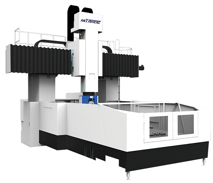
As the core equipment in the field of high-end mechanical processing, the five-axis gantry machining center is the result of the deep integration of technologies in multiple fields such as machinery, electronics, and computers. It is based on a stable gantry frame. In addition to the three linear motion axes of X, Y, and Z, it is also equipped with two rotary axes. Common rotary axis combinations include A/B axis, A/C axis, or B/C axis. The addition of these two rotary axes gives the tool or workpiece the ability to achieve multi-angle and multi-directional movement in space, allowing it to approach the workpiece in a more flexible posture, thereby achieving high-precision processing of complex-shaped workpieces.
Compared with ordinary machining centers, the five-axis gantry machining center has significant advantages. In terms of machining accuracy, the characteristic of completing multi-faceted machining in one clamping effectively reduces the number of clamping times and positioning errors of the workpiece. For example, when machining large box-type parts, ordinary machining centers require multiple clampings, and the cumulative error may affect the accuracy of the parts, while the five-axis gantry machining center can avoid such problems and greatly improve the machining accuracy. In terms of processing efficiency, reducing the number of clamping times saves time, and the five-axis linkage function allows the tool to move along a more optimized path, shortening the processing cycle. At the same time, with the five-axis linkage function, it can process free-form surfaces, complex cavities and other shapes that are difficult to complete with traditional processing methods. Parts with twisted surfaces such as impellers and turbines can also be accurately formed under the five-axis gantry machining center.
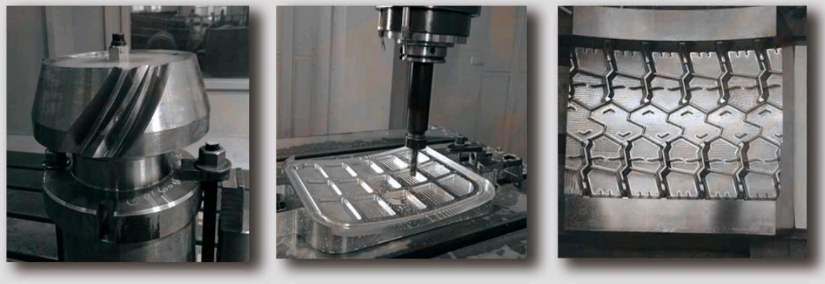
The Samples
In the field of aerospace, the five-axis gantry machining center plays an irreplaceable role. In order to meet aerodynamic requirements, aircraft engine blades have complex surface shapes and strict precision standards. The five-axis gantry machining center can accurately process blades by precisely controlling the tool path, ensuring its aerodynamic performance and ensuring the efficient operation of the engine. In automobile manufacturing, it is not only used to process engine cylinders, but also to manufacture high-precision automobile molds. Taking automobile cover molds as an example, the five-axis gantry machining center can quickly and accurately process the complex surfaces of the mold, improve the quality and production efficiency of automobile parts, and help optimize the appearance and performance of the car. In the mold manufacturing industry, whether it is a precision injection mold or a die-casting mold, the five-axis gantry machining center can quickly produce molds that meet the requirements with its high precision and high efficiency, greatly shortening the mold development cycle and improving the company’s market competitiveness. In addition, in the field of shipbuilding, it can be used to process complex parts such as ship propellers; in the medical device industry, it can process high-precision orthopedic implants; in high-end equipment manufacturing, it also provides reliable guarantees for the processing of various complex parts, and promotes the development of various industries towards high precision and high efficiency in all directions.
| Product Model | GMC2040u/t | unit | ||
| Workbench | Workbench size | 2000×4000 | mm | |
| Distance between two columns | 2400 | mm | ||
| Workbench load-bearing | 14000 | Kg | ||
| Processing range | Working table front and rear moving distance (X axis) | 4200 | mm | |
| The distance the skateboard moves left and right (Y axis) | 2600 | mm | ||
| Ram up and down movement distance (Z axis) | 1 4 00 | mm | ||
| Spindle head A axis swing angle | ±105 | º | ||
| Spindle head C axis rotation angle | ±360 | º | ||
| Distance from spindle end to worktable when spindle is vertical | Maximum | 1 5 00 | mm | |
| Minimum | 100 | mm | ||
| Distance from spindle center to table when spindle is horizontal | Maximum | 1 8 40 | mm | |
| Minimum | 440 | mm | ||
| Spindle | Cone hole | HSK-A100 | ||
| Speed range (stepless) | 150~15000 | r/min | ||
| Maximum output torque | 120/145 (S1/S6) | Nm | ||
| Spindle motor power | 45/45 (S1/S6) | kW | ||
| A-axis maximum torque | 1200 (2160 when clamped) | Nm | ||
| C-axis maximum torque | 1100 (3024 when clamped) | Nm | ||
| Ram cross-sectional area | 460×460 | mm | ||
| Tool magazine (Okada) | Form/Capacity | Chain 40 | ||
| Maximum tool length | 350mm | |||
| Maximum tool diameter (full tool) | Φ100 | |||
| Maximum tool weight | 2 5 Kg | |||
| Tool change time (knife to tool) | 20S | |||
| Feed | Cutting feed speed range | X-axis | 1~10000 | mm/min |
| Y and Z axis | 1~20000 | mm/min | ||
| A, C axis | 60 | r/min | ||
| Fast Movement | X-axis | 20000 | mm/min | |
| Y and Z axis | 25000 | mm/min | ||
| A, C axis | 60 | r/min | ||
| Positioning accuracy | X-axis | Implementation standard VDI/DGQ3441 | 0.025 | mm |
| Y-axis | 0.015 | |||
| Z-axis | 0.01 | |||
| A/C axis | 8 | ″ | ||
| Repeat positioning accuracy | X-axis | Implementation standard VDI/DGQ3441 | 0.008 | mm |
| Y-axis | 0.008 | |||
| Z-axis | 0.008 | |||
| A/C axis | 5 | ″ | ||
| Machine weight | 50 | t | ||
| Total electrical capacity | 130 | KVA | ||
| Machine tool dimensions (length × width × height) | 12000×6500×6800 | mm | ||
If you also have a need for a five-axis machining center, please consult ANTISHICNC, we will provide you with professional advice! Please contact contact@antsmachine.com