| Boring shaft | Boring bar diameter | mm | 130 |
| Spindle bearing inner diameter | mm | 140 | |
| Taper standard | 7/24;BT50 | ||
| Spindle speed range | rpm | 35-2500 | |
| Spindle drive system | Z.F gearbox | ||
| (cont./30min) spindle power | Kw | 22/26 | |
| The maximum output torque of the main shaft | Nm | 1460 | |
| Spindle maximum continuous output torque | Nm | 1230 | |
| transmission ratio | 1:1.6;1:5.5 | ||
| Travel | X-axis travel | mm | 3000 |
| Y-axis travel | mm | 2000 | |
| Z axis travel | mm | 1500 | |
| W axis travel | mm | 700 | |
| B-axis indexing | deg | 0.001 | |
| Distance from spindle center to table surface | mm | 0-2000 | |
| Distance from spindle nose to table center | mm | 200-2400(Z1500) | |
| Worktable | Work surface size | mm | 1600×1800 |
| Maximum load of workbench | ton | 12 | |
| T-slot | mm | 22(H7)×200×8 | |
| Axial screw | X-axis ball screw dimensions | mm | 63×P20×C3, double nut |
| Y-axis ball screw dimensions | mm | 63×P20×C3, double nut | |
| Z-axis ball screw dimensions | mm | 63×P20×C3, double nut | |
| W-axis ball screw dimensions | mm | 40×P10×C3,single nut | |
| Axial guide | X axis rail | RGR55H | |
| X-axis rail span | mm | 1000 | |
| Y-axis hard track width | mm | 180×2 | |
| Y-axis guide rail span (inner/outer distance) | mm | 520/880 | |
| Z axis rail | RGR65H | ||
| Z-axis guideway span | mm | 1000 | |
| Axial displacement | Maximum rapid displacement X/ Y/ Z/W | m/min | 10/10/10/8 |
| Maximum cutting displacement X/ Y/ Z/W | m/min | 10/10/10/5 | |
| B-axis speed | rpm | 2.5 | |
|
Axial Motor & Torque |
X-axis motor & torque & reduction ratio | KW & Nm | 7 & 30 (1:4) |
| Y-axis motor & torque & reduction ratio | KW & Nm | 7 & 30 (1:4) | |
| Z axis motor & torque & reduction ratio | KW & Nm | 7 & 30 (1:4) | |
| W-axis motor & torque | KW & Nm | 4 & 22 | |
| B-axis motor & torque | KW & Nm | 7 & 30 | |
|
Accuracy (ISO230-2,2006) |
Positioning accuracy (X, Y, Z) | mm | 0.015 |
| Repeat positioning accuracy (X , Y , Z) | mm | 0.012 | |
| Positioning Accuracy (W) | mm | 0.02 | |
| Repeatability (W) | mm | 0.012 | |
| Positioning accuracy (B)
4×90° |
Second | 15
±4 |
|
| Repeatability (B)
4×90° |
Second | ±5
±2 |
|
|
Tool magazine (optional) |
Magazine capacity | PCS | 40 |
| Maximum Tool Diameter | mm | 125 | |
| Maximum tool diameter, adjacent tools are empty | mm | 245 | |
| tool length | mm | 500{700} | |
| tool weight | Kg | 25 | |
| Tool to tool change time | Second | 16 | |
| Gas source | barometric pressure | Bar | 5-7.5 |
| air flow volume | L/min | 250 | |
|
lubricating |
pump motor | W | 25 |
| pump pressure | Kg/c ㎡ | 20 | |
| pump capacity | c.c./min. | 250 | |
| Coolant | pump motor | KW | 1.7 |
| Tank capacity | L | 400 | |
|
Others
|
Electricity demand | KvA | 100 |
| Machine height | mm | 5300 | |
| Machine weight | Kg | 34,000 | |
| Machine tool/foundation footprint | mm | 6920×8393/5670×6695 |
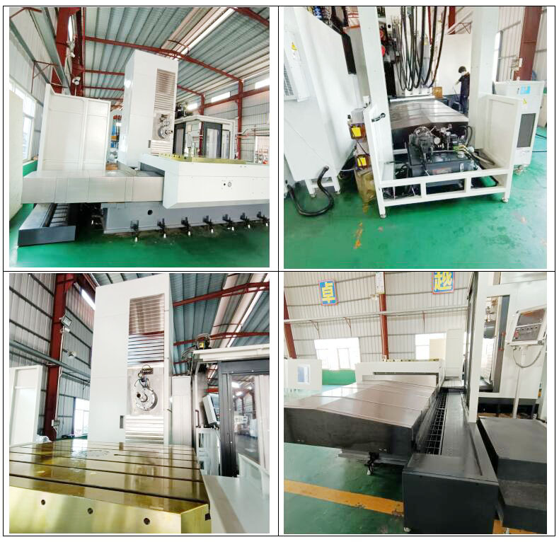
Equipment Introductions
1. Main casting
The most advanced computer technology and optimized finite element analysis method are used in the design, so that the major components of the machine tool can bear the maximum load as much as possible, the design is reasonable, and the material selection is exquisite. All castings are made of high-strength Meehanite cast iron with grade H300, so the whole machine tool has excellent rigidity, stability and precision retention, and is especially suitable for heavy cutting. All large-scale castings have undergone strict annealing treatment, coupled with long-term natural aging, to completely eliminate internal stress and greatly improve the accuracy of the whole machine. The processed parts have excellent geometric shape and position accuracy. baked) castings, one-piece casting, wear-resistant, after internal force relaxation treatment, so that it can achieve high vibration resistance, its shock absorption capacity is 10 times higher than ordinary cast iron, which improves the stability of the machine tool, the machine tool base is a “T” shape structure, Distance-shaped force design, stable organization, and permanent quality maintenance.
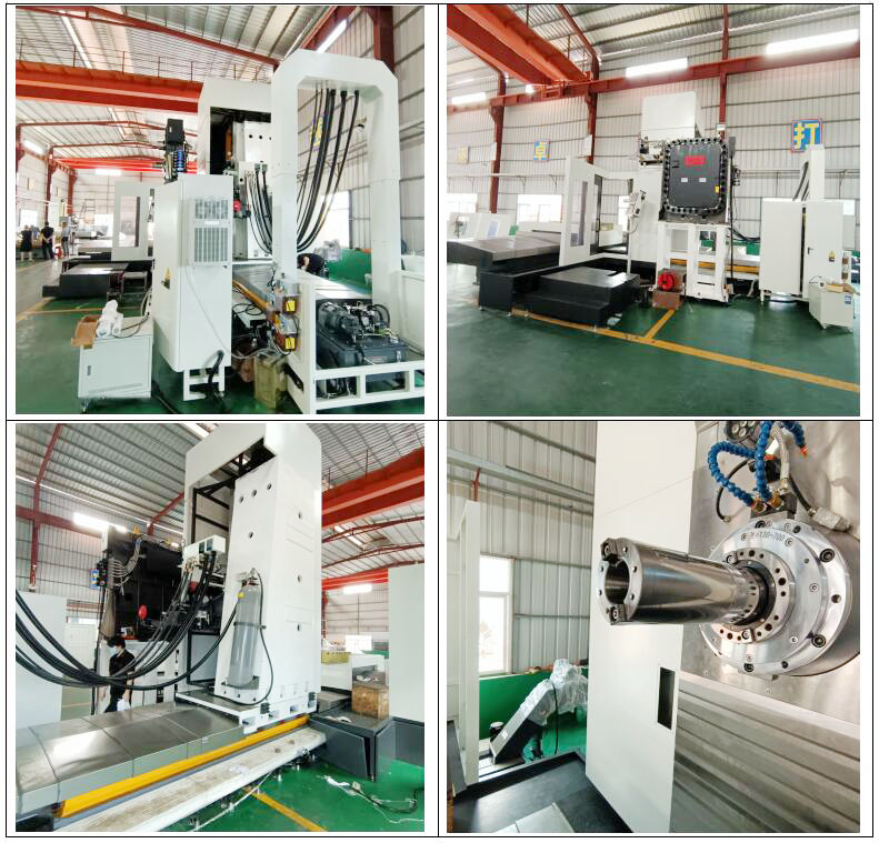
2. Column
Column mobile heavy cutting structure, column guide rail adopts rectangular hard rail design, guide rail surface is subjected to high-frequency heat treatment, surface hardness HRC55°, high-precision surface grinding treatment, full stroke straightness within 15µm, sliding surface is pasted with Italian 1.2mm wear-resistant sheet , making the surface of the guide rail more smooth and wear-resistant. The widened hard rail design can ensure the resistance and stability required by the machine during heavy cutting.
3.Spindle, Headstock
3.1. The head-stock is specially designed with high-strength, high-rigidity cage and keel rib structure, with a hardness of HRC52-55. The main shaft gear box adopts the German Z.F brand. Ideal transmission precision and large torque can be obtained.
3.2. The spindle boring bar is independently developed by our company (patent applied for). The push-pull seat adopts two sets of angular contact ball bearings to increase the supporting rigidity of the boring bar. The eccentric moment of the boring bar is small and the radial bearing capacity is strong.
3.3. The steel sleeves at the front and rear ends of the main shaft are equipped with automatic lubrication devices to keep the boring bar continuously lubricated, not easy to rust and wear, and the load is small and stable.
3.4. W-axis feed support: two 35-roller linear guide rails, 5010 ball screw C3 grade is used as the transmission shaft, the end of the screw rod is designed with a pre-tensioned end, and the motor is directly connected to the drive.
3.5. At the lower end of the guide rail of the spindle box, a graphite copper plate is installed to make the surface of the guide rail more wear-resistant. The hollow spindle adopts German MM technology and is made of chrome-molybdenum alloy steel. It is tempered, rough and finished, carburized, aged and precision ground. It has high precision, strong rigidity and is not easy to deform. Motor power (22/26kw), boring bar diameter 130mm, maximum speed 2500RPM.
After the main shaft is assembled, it is corrected by dynamic balance test. The weight balance of the headstock adopts nitrogen oil pressure counterweight design to further improve the stability of the headstock during operation.
4.Working table (independent research and development patent) strengthened structure, strong bearing capacity (load 12T) continuous rotary table, 0.001°segmentation accuracy, automatic hydraulic locking positioning, digital control AC servo motor with gear transmission, double lead worm Drive helical worm gear to achieve good backlash compensation; digital information feedback is quick and repeat positioning accuracy is high.
5. Guide
The X and Z-axis slide rails adopt international heavy-duty linear roller guide rails (X-axis slide block 55mm, Z-axis slide block 65mm wide), the X and Z axes use two roller-type line rails, and use 8 sliders together, which has good rigidity, high precision and long service life. The Y-axis direction adopts a V-shaped box design to provide stronger rigidity, and the guide rail is covered with wear-resistant sheets, and the surface hardness is HRC52-55. When moving axially, lubricating oil is pumped out from the outlet to the oil groove to cover the entire support surface, which can greatly improve the precision retention of the machine.
The X and Z axes adopt a diameter of φ63㎜ (φ63XP20), and the Y axis adopts a diameter of φ63mm (φ63XP20). C3 grade precision ball screw and P4 grade bearing have good positioning accuracy. The ball screw is covered by a sheet metal airtight cover, which is not easily corroded by cutting water and iron filings. Each axis is driven by a servo system, which has the advantages of rapid transmission, stable precision, elimination of backlash, improvement of torsional rigidity, non-parallel allowable angles, elimination of axial errors, etc., which greatly improves the positioning accuracy of the machine tool.
6. Grating ruler
The linear axes X, Y, and Z are all equipped with Spanish Fagor absolute grating scales, with a resolution of 0.001mm, fully closed-loop control, quick digital information feedback, and high repeat positioning accuracy.
7. Lubrication
The automatic lubricating system adopts the volumetric oil injector BTA-A2P-3L220V to control the oil volume according to the metered distribution value. Oil is supplied according to the lubricating oil demand of the sliding surface and ball screw, and an oil level detector is provided. When the oil quantity is short, an alarm will be displayed on the screen. Sealed spindle bearings are lubricated with grease. Boring bars with automatic lubrication.
8. cooling system
The cooling water tank adopts a split design, which makes it easy to clean chips and replace cooling water. Water tank capacity up to 400 liters.
9. Chip removal device
The spiral chip remover is installed behind the X-axis base, which can easily remove a large number of iron chips falling in the processing area.
10. Chip Conveyor & Chip Receiver
The chip conveyor is located on the left side of the machine tool, which can effectively remove iron chips. Offers hinged conveyor belts for cleaning of iron filings, metal, aluminum, and non-ferrous filings. There is also a crumb trolley for easy cleaning.
11.Electrical unit
Power supply units, switch-gear, safety and protection components and other electrical components are housed in the electrical cabinet. The main components are all selected from famous brands in the world. In the electrical cabinet, the circuit control voltage is 24V and complies with CE standards. All CE certified electrical components, electrical diagrams, safety guards and PLC comply with CE regulations.
12. Electric cabinet air conditioner
Keep the temperature inside and outside the electrical cabinet the same. Prevent components in the electrical cabinet from being damaged due to high operating temperature.
Main Parts & Standard Equipment
| Rigid tapping, helical interpolation | FANUC 0i MF PLUS CNC system |
| Column mobile heavy cutting structure | Table B-axis 0.001° division |
| Spindle oil temperature cooling device | Spindle type: BT-50 |
| Air blowing device inside the spindle | 10.4 inch color screen display |
| Sliding surface automatic lubrication system | Boring bar shaft diameter: ф 130mm |
| Automatic protection power-off device | Anchor screws and shims |
| Built-in spiral chip removal device | RJ45 interface, USB interface, Ethernet interface |
| Cutting Oil Unit | X , Y , Z , B , W five-axis four-linkage function |
| Electrical control box | X, Y, Z, axis closed-loop control (Fager grating ruler) |
| Electrical box air conditioner | B-axis closed-loop control (Fager angle encoder) |
| Cutting cooling water system | X, Z axis roller rail, Y axis wide hard rail |
| External hand wheel | Working light |
| Toolbox | task lighting |
| Operating system parameter CD | Machine Manual |
| Machine system data (electronic version) | Machine tool precision factory inspection report (electronic version) |
| Transformer | External crawler chip conveyor and chip accumulator trolley |
Machine Optional Parts:
1. 130 Spindle Extension Support Protection Sleeve (φ170, L240mm)
2. 40 chain tool magazines
3. Spindle center outlet water 20/70BAR
4. Open top protection device for workbench
5. Operator protection device
6. Manual right-angle milling head (including extension body)
7. Flat rotating disk
8. A-axis rotary table and center frame, bracket, tail-stock
Product reference picture