1. Preface
In the high-precision, high-quality, and high-efficiency processing of parts and components, measurement technology plays a very important role. Due to differences in the blanks, it is difficult to rely on the machine tool itself to control the machining accuracy. Real-time measurement of workpieces with precision probes is an important part of the machining process of machine tools. The principle of the measurement system is shown in Figure 1.

As the signal sensing component of the measurement system, the probe can enable the machine tool to realize automatic measurement of the processing size during the processing of the blank. After the machine tool processes and analyzes the measurement results fed back by the probe, it automatically modifies the processing program to improve the processing accuracy. The CNC machine tool not only has the machining function, but also has the function of the measuring machine, which further improves the processing performance.
2. Integration of probe measuring device and CNC system
Active measurement technology is widely used in powertrain machining lines of automobile companies. For example, the MARPOSS T25 probe and P1SRW60000 receiver introduced by the machining equipment of the cylinder block and cylinder head production line, combined with the Siemens SINUMERIK 840D sl high-end CNC system, the probe and The CNC system connection application can realize the workpiece measurement function. The cold and hot state of the machine tool has a greater impact on the key dimensions, and it is very important to eliminate errors by measuring with a probe. MARPOSS T25 probe is a trigger probe, which uses radio transmission to trigger the probe system transmission mode. When the system executes the measurement action, the T25 probe sends out a sampling pulse signal. After the receiving device receives the signal, it is transmitted to the NCU (Numerical Control Unit, central control unit). After calculation and analysis, the NCU determines whether the coordinate deviation of the workpiece or fixture is within the specified tolerance Within the range, and automatically correct the offset of the coordinate system according to the measurement results, so that the same machine tool can process more high-precision parts.
2.1 Hardware composition and parameter setting
The measuring device used in this case is MARPOSS T25 probe and P1SRW60000 receiver, which cooperates with Siemens SINUMERIK 840D sl high-end CNC system. The MARPOSS probe system consists of a transmitter and a radio receiver with an integrated interface. It is suitable for medium and large machine tools and five-axis machine tools; its sturdy and stable design can adapt to harsh processing environments; the transmission frequency is 2.4GHz, and the transmission distance is as long as 15m. And has excellent anti-interference.
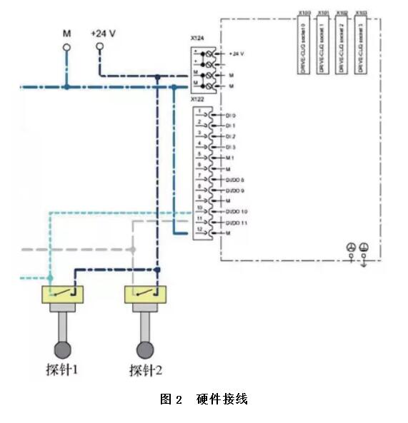
The CNC unit of SINUMERIK 840D sl, as the central control unit of the CNC machine tool, is responsible for the logic control functions of the entire machine tool. It is mainly composed of a COM CPU board, a PLC CPU board and a DRVIVE board. The hardware wiring is shown in Figure 2. The spindle 1 probe receiver corresponding to probe 1 is connected to the 10-pin port on the X122 interface unit of the NCU, and the spindle 2 probe receiver corresponding to probe 2 is connected to the X122 interface unit 11-pin port on the top. By modifying SINUMERIK 840D sl parameter P680, you can manually set the measurement input interface. In addition, MD13200 can be configured to be active in high and low levels.
After the system is normally connected and powered on, use the M command to start the probe in MDA or automatic mode, and the measurement input of probes 1 and 2 can be monitored by the DB10.DBX107.0 and DB10.DBX107.1 on the PLC side. The double-spindle machine tool has two independent Z-direction feeds, sharing the X and Y-direction feeds. When measuring, X, Y, Z1 are the first set of probe systems, and X, Y, Z2 are the second set of probe systems, which are measured separately.
2.2 PLC control program
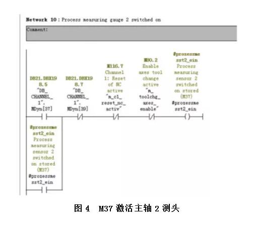
The PLC program activates the function of the spindle 1 probe through M38 (see Figure 3), the function of activating the spindle 2 probe is completed through the control of M37 (see Figure 4), and the PLC control M39 can turn off all the probe functions. When the NCU side receives an M function, the corresponding signal function on the PLC side will be activated, so as to realize the information exchange between the NCU and the PLC, and activate or deactivate the auxiliary functions of the machine tool such as enabling or disabling the measuring head.
When the NCU accepts the M38 function request, it activates the spindle 1 probe. Only when the probe is activated, can the next instruction be executed, otherwise the measurement data may be inaccurate because the probe is not fully activated. Since M0~M99 are dynamic M functions and generally do not have the read-in prohibition function, the read-in prohibition function should be added to the PLC after the M38 function is executed. When the M38 function is executed, a 510116 operation message will be generated, indicating that the probe is in the open state. . When the probe is successfully activated, if the condition of the operation information does not satisfy the logical relationship, it will automatically disappear from the HMI. According to the prompt information of the Doconcd manual, the operation information of 510116~510123 has the functions of reading prohibition and feed prohibition. Use these special operation information to make M38 (activate the spindle 1 probe function) and M37 (activate the spindle 2 probe function) have the functions of reading prohibition and feed prohibition, ensuring that the measurement is performed after the activation is completed, thereby ensuring the measurement result Accuracy.

2.3 NC control program
1) Move the axis to the actual position on the measuring workpiece. When the measuring head has a pulse edge, delete the remaining stroke between the actual position and the given position, and write the actual position of the axis into the storage unit.
2) Set the tolerance zone of the measured value. When the GUD global variable measurement value M E A S U R I N G_VA L U E_Z exceeds UPPER_TOLERANCE_LIMIT or is less than LOWER_TOLERANCE_LIMIT, NC alarm 65952 is output.
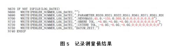
3)Record the measurement result value. Use the WRITE instruction to write the paragraph or data in the part program to the end of the specified file (log file). Use this function to record the measurement results of the two probes (see Figure 5), and the semicolon is used as a separator for separation and stored in the subprogram folder. Use U disk to copy these files and open them directly in the computer Excel table. Check the semicolon as the separator. In the preview window, you can see that the measurement results are clearly displayed in the Excel table, which is convenient for managing the data of the measured values and ensuring that the data is available. Retrospective.
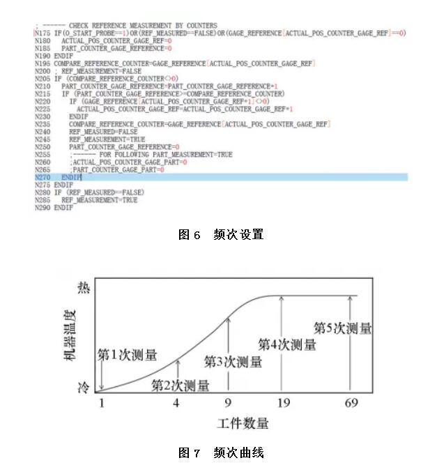
4)Measurement frequency setting. In actual production, not every work piece is measured. In this example, the interval between the measuring pieces will be increased by setting (see Figure 6). During the machining center from cold to warm, the measured value will fluctuate. When the machining center is warmed up, the measured value will become stable. At this time, there is no need for small frequency measurement. The frequency curve is shown in Figure 7.
5) Correct the coordinate system. The compensation value obtained after measurement can be written into each coordinate system of the dual-spindle through the CFINE fine offset command to modify the coordinate system compensation function. The coordinate system compensation value of a double-spindle machine tool has four directions: X, Y, Z1, and Z2, which correspond to variables R320, R321, R322, and R323 in the program, respectively.
2.4 Software monitoring
SinuCom NC is a tool for analysis and management of Siemens 840D sl CNC system and drive data. The software package supports simple and efficient debugging of the SINUMERIK 840D sl control system. The included program provides a wealth of machine tool debugging products, including tracking functions, safety integrated acceptance testing, PC card image file generation, serial debugging management, and CNC user data transmission.
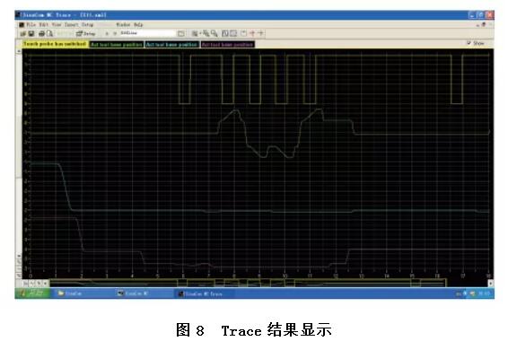
SinuCom NC software provides many diagnostic and debugging tools, such as FFS, ARC, Trace, etc. Among them, the Trace function can monitor system status, IO status, servo functions, PLC/NC variables, etc. in an all-round way. Probe signals are added to the software, and variables can be recorded by events or manual triggers. Through these records, users can easily monitor the running status of the probe, and it is also convenient for users to diagnose faults.
Complete the configuration in SinuCom NC Trace, and then run the configuration into the system, the Trace result will be automatically displayed in SinuCom NC Trace, as shown in Figure 8.
3. Concluding remarks
The dual-spindle machining center of the 840D sl CNC system with a dual-probe measurement system has achieved good results and will be gradually extended to dual-spindle projects in other workshops. In the actual commissioning process of the project, the flexibility and openness of the 840D sl CNC system, as well as complete technical data and good technical support, ensured on-site commissioning and reduced project costs.