


1 Introduction
The bell-shaped shell is a series of products produced for supporting the steering gear of automobiles and forklifts. The shape of the shell varies greatly and the size varies greatly. There are shank and without shank; there are ball and cylindrical heads; the diameter range of the inner spherical surface is S4> 50-160m, the grinding width is 20-85m; the positioning outer diameter is 080-200m, and the total length of the workpiece is up to 570m . Based on the above situation, we have designed an elastic fixture that meets the bearing accuracy level.
Electromagnetic centerless clamps are usually used for grinding cylindrical or circular bearing rings. For bell-shaped shell bearings with handles, electromagnetic centerless clamps cannot be used for positioning and clamping. Two main problems need to be solved when centering fixtures are used on high-precision grinders:
One is how to ensure the coaxial problem of the inner spherical surface of the bell-shaped shell processing and the assembly reference surface in the use of the bell-shaped shell; the second is to keep the rotation of the bell-shaped shell workpiece stable and unchanging under the action of grinding resistance.
After a lot of production practice tests, the “elastic fixture” we designed and developed can well solve the problem of grinding and clamping the spherical surface of the bell-shaped shell. Combining the existing common bell-shaped shell workpiece types and the base surface characteristics of different forms of bell-shaped shells, we have carefully designed different positioning surfaces and clamping schemes. Based on the similar basic structure, the same basic functions, and the sharing of basic original parts, we have developed five specific application modes, which not only enhance the practicability, but also take into account the versatility of the parts, simplify the structure, and reduce the enterprise’s cost. Application cost improves the autonomy and enthusiasm of workers.
2.The structure of the elastic clamp
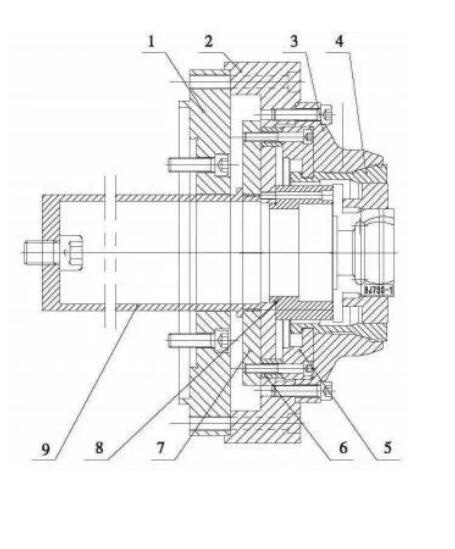
Figures 1-5 are elastic clamps specially designed for the structural features of different bell-shaped shell workpieces. The connecting plate is connected to the hollow workpiece shaft, thereby driving the entire fixture and the clamped workpiece to rotate with the workpiece shaft during grinding; the connecting seat is the seat body of the elastic fixture. The conical surface of the inner surface of the clamp seat matches with the conical surface of the elastic chuck to ensure accurate clamping and positioning of the workpiece; the pull plate is clamped on the elastic chuck and connected to the pull plate through the contour guide sleeve; the pull plate is connected to the pull sleeve , The pull sleeve is connected to the rotary cylinder, and the pull sleeve, pull plate, contour guide sleeve, pull plate and elastic chuck are driven to complete the loose and tight movement through the extension and contraction of the rotary cylinder fixed on the workpiece shaft; It is used to ensure accurate positioning of the workpiece during clamping; the clamping process ring is used when the diameter of the positioning end of the workpiece is larger than the diameter of the clamping part to ensure that the workpiece can also be installed.
Details are as follows :
Figure 1 The positioning and clamping of a cylindrical workpiece without a shank, the method is to locate the rear surface of the bell-shaped shell and clamp the cylindrical surface. The connecting plate 1 is connected to the hollow workpiece shaft, thereby driving the entire fixture and the clamped workpiece to rotate with the workpiece shaft during grinding; the connecting seat 2 is the seat body of the elastic fixture; the fixture seat 3 has an inner surface The tapered surface of the chuck matches the cone of the elastic chuck 4 to ensure accurate clamping and positioning of the workpiece; the pull plate 5 is clamped on the elastic chuck 4 and is connected to the pull plate 7 through the contour guide sleeve 6; the pull plate 7 is in turn connected to the elastic chuck 4 The pull sleeve 9 is connected, and the pull sleeve 9 is connected to the rotary cylinder. The pull sleeve 9, the pull plate 7, the contour guide sleeve 6, the pull plate 5 and the elastic chuck are driven by the extension and contraction actions of the rotary cylinder fixed on the workpiece shaft. 4 Complete the loose and tight actions; the end face positioning 8 is used to ensure the accurate positioning of the workpiece during clamping.
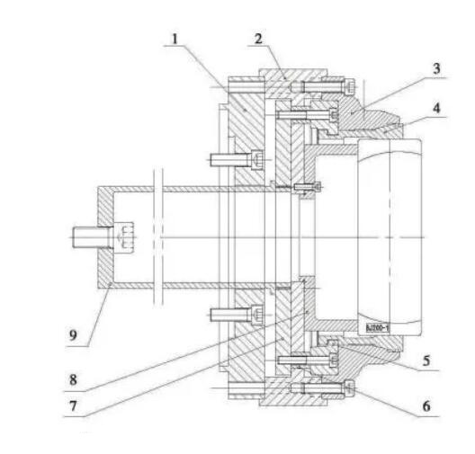
Figure 2 Positioning and clamping of a shank ball-head-shaped workpiece is to locate and clamp the outer spherical surface on the end surface of the ball-head. The connecting plate 1 is connected to the hollow workpiece shaft, thereby driving the entire fixture and the clamped workpiece to rotate with the workpiece shaft during grinding; the connecting seat 2 is the seat body of the elastic fixture; the inner surface of the fixture seat 3 The tapered surface matches the tapered surface of the elastic chuck 4 to ensure accurate clamping and positioning of the workpiece; the pull plate 5 is clamped on the elastic chuck 4 and is connected to the pull plate 7 through the contour guide sleeve 6; the pull plate 7 is in turn connected to the pull sleeve 9 is connected, the pull sleeve 9 is connected to the 9 rotary cylinder, and the pull sleeve 9,
The pull plate 7, the contour guide sleeve 6, the pull plate 5 and the elastic chuck 4 complete the tightening action; the end face positioning 8 is used to ensure the accurate positioning of the workpiece during clamping.
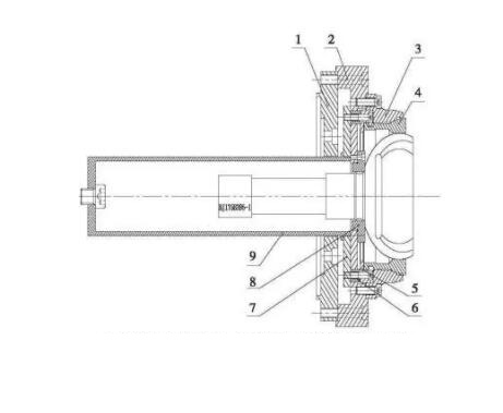
Figure 3 Positioning and clamping of a ball-shaped workpiece with a handle is to locate and clamp the outer spherical surface on the end face of the handle. The connecting plate 1 is connected to the hollow workpiece shaft, thereby driving the entire fixture and the clamped workpiece to rotate with the workpiece shaft during grinding; the connecting seat 2 is the seat body of the elastic fixture; the inner surface of the fixture seat 3 The tapered surface is matched with the tapered surface of the elastic chuck 4 to ensure accurate clamping and positioning of the workpiece; the pull plate 5 is clamped on the elastic chuck 4, and is connected with the pull plate 7 through the waiting guide sleeve 6; the pull plate 7 is connected to the pull sleeve 9 is connected, the pull sleeve 9 is connected to the rotary cylinder, and the pull sleeve 9, the pull plate 7, the contour guide sleeve 6, the pull plate 5 and the elastic chuck 4 are completed by the extension and contraction actions of the rotary cylinder fixed on the workpiece shaft. Loose and tight actions; end face positioning 8 is used to ensure accurate positioning of the workpiece during clamping.
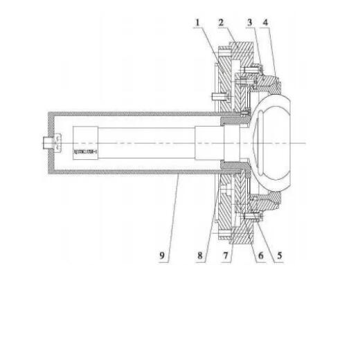
Figure 4 Positioning and clamping of a shank-shaped work piece with a ball head, the method is to locate and clamp the cylindrical surface of the ball head on the end surface of the ball head. The connecting plate 1 is connected to the hollow workpiece shaft, thereby driving the entire fixture and the clamped workpiece to rotate with the workpiece shaft during grinding;
The connecting seat 2 is the seat body of the elastic clamp; the tapered surface of the inner surface of the clamp seat 3 matches the tapered surface of the elastic chuck 4 to ensure accurate clamping and positioning of the workpiece; the pull plate 5 is clamped on the elastic chuck 4 and passes through the same height The guide sleeve 6 is connected with the pull plate 7; the pull plate 7 is connected with the pull sleeve 9, and the pull sleeve 9 is connected to the rotary cylinder. The pull sleeve 9 and the pull plate 7 are driven by the extension and contraction actions of the rotary cylinder fixed on the workpiece shaft. , The contour guide sleeve 6, the pull plate 5 and the elastic chuck 4 complete the action of loosening and tightening; the end face positioning 8 is used to ensure the accurate positioning of the workpiece during clamping.
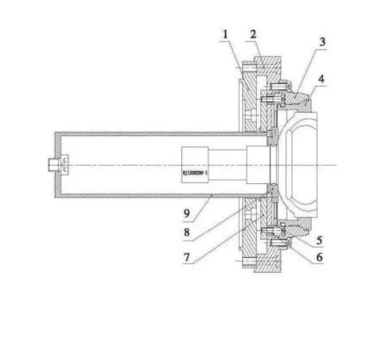
Figure 5 Positioning and clamping of a workpiece with a stepped shape without a shank and a clamping outer diameter smaller than the outer diameter of the positioning surface. The method is to position the end face and clamp the cylindrical surface of the workpiece through the clamping process ring. The connecting plate 1 is connected to the hollow workpiece shaft, thereby driving the entire fixture and the clamped workpiece to rotate with the workpiece shaft during grinding; the connecting seat 2 is the seat body of the elastic fixture; the inner surface of the fixture seat 3 The tapered surface is matched with the tapered surface of the elastic chuck 4 to ensure accurate clamping and positioning of the workpiece; the pull plate 5 is clamped on the elastic chuck 4 and is connected to the pull plate 7 through the contour guide sleeve 6; the pull plate 7 is in turn connected to the pull sleeve 9 is connected, the pull sleeve 9 is connected to the rotary cylinder, and the pull sleeve 9, the pull plate 7, the contour guide sleeve 6, the pull plate 5 and the elastic chuck 4 are completed by the extension and contraction actions of the rotary cylinder fixed on the workpiece shaft. Loose and tighten actions; end face positioning 8 is used to ensure accurate positioning of the workpiece during clamping; clamping process ring 10 is used when the diameter of the positioning end of the workpiece is larger than the clamping part to ensure that the workpiece can also be installed.
It can be seen from the application of several elastic fixtures as shown in Figure 1-5 that the method of replacing a few tooling parts (such as end face positioning 8) is suitable for the situation of large changes in the shape of the workpiece and large differences in size, which can achieve rapid and reliable positioning of the workpiece. Ensure a successful clamping.
3.Application and effect
4.The fixture is mainly used on the spherical grinder in the CNC bell-shaped shell. The use of this elastic fixture to clamp the workpiece ensures that the CNC grinder has fast clamping, accurate positioning and reliable performance when processing the bell shells of the steering gear of automobiles and forklifts, so that the product meets the accuracy requirements and the quality is stable. This kind of bell shell is a series of products produced by a bearing factory for supporting automobile and forklift steering gears. The technical application effect is good, and it has been widely praised by customers.
4 Conclusion
The development of fixtures and machine tools mentioned in the article provides solutions and equipment for the processing of bell-shaped shell series products of this kind of supporting automobile and forklift steering gears, which has reached the processing accuracy of similar foreign equipment, and is in a leading position in my country. The localization of auto parts products has contributed.