


Ordinary turning tools are mainly used for rough and fine turning of the inner and outer surfaces and end faces of various parts, and reach the size, form and position tolerance accuracy and surface quality required by the drawing.
Ordinary turning tools are classified according to the compaction method, including D-type compaction, lever compaction, screw compaction, plate compaction, compound compaction and other forms. Type D compression is shown in Figure 3-11a, and double-sided blades with negative rake angles can be used. In turning, stability and safety are key factors, and the reliable clamping of the blade will have a huge impact on the surface quality of the part. The D-type compression system combines the downward clamping force with the positioning of the blade seat. It not only effectively ensures the rigid clamping of the blade, but also has high repeatability when the blade is indexed. The lever compression is shown in Figure 3-11b, using single-sided or double-sided blades with negative rake angles in ISO standards. The lever compression structure can obtain the most ideal three-way clamping force (downward and to both sides of the blade), and it also has the advantages of convenient and quick removal of the blade and smooth chip removal. The disadvantage is that the rigidity is poor and the clamping stroke is short. It is difficult to remove chips from damaged levers and screw wrench holes. Mainly used for the cutting of medium and small machine tools, it is currently the most commonly used structure of indexable turning tools in domestic and foreign turning. Screw compression is shown in Figure 3-11c. Compared with the Type D compression system, it has the advantages of simple structure, convenient operation, more stable and smooth chip flow, and the ability to use various blade shapes. The disadvantage is that the impact resistance is poor, and the screw pressing system is the first choice for external and internal hole cutting with positive rake angle inserts in medium and small machine tools. The pressing plate is shown in Figure 3-11d and Figure 3-11e. Its advantages are large clamping force and simple structure; its disadvantage is that it affects chip flow, and is mainly used for medium, heavy and intermittent cutting conditions. Compound compression is shown in Figure 3-11f. Its advantage is that it is reliable in clamping and can withstand large cutting loads and impacts. The disadvantage is that the pressure plate will affect the flow of chips and is mainly used for heavy cutting conditions.
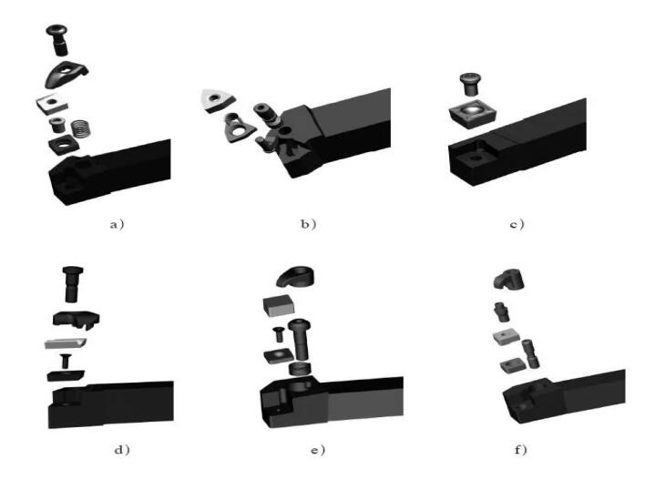
Figure 3-11 Ordinary turning tool pressing method
a) D type compression b) lever compression c) screw compression d) compression plate compression (alloy blade) e) compression plate compression (ceramic blade) f) composite compression
(1) External turning
Ordinary external turning is to process the external surface of the part to obtain the required size, shape and position accuracy and surface quality. Ordinary external turning tools are divided into 95°, 90°, 75°, 60°, 45°, etc. according to the entering angle of the tool. When cutting with 90°, 95° entering angle tools, the axial force is large, but the radial force is small. , Suitable for turning slender shaft parts, 75°, 60°, 45° entering angle tools are suitable for turning the outer circle of short and thick parts, of which 45° entering angle tools can also be used for 45° chamfer turning. The economics of turning tools with negative-angle inserts is better than turning tools with positive-angle inserts, while positive-angle inserts have sharp cutting edges and fast cutting. However, the size of positive-angle inserts is generally small, which is only suitable for small-back tooling and small-feed processing. , And negative-angle blades can be made larger in size, which can be used for large-back tooling and large-feed processing, and the strength of the blade should be better than that of the positive-angle blade (the blade with the same shape, size, and arc of the blade). Different shapes of blades have different edge strengths, different effective cutting edge lengths, and different number of available tool tips.
(2) End turning
Face turning refers to the main cutting edge cutting the end face of the workpiece.
1. Matters needing attention when car end face
(1) The tip of the turning tool should be aligned with the center of the workpiece to avoid leaving a boss in the center of the turning end face.
(2) On the end face of the partial tool turning, it is easy to pierce the knife when the amount of the knife is large. The selection of the amount a of the back knife: a=0.5~3mm for rough turning, ap=0.05~0.2mm for fine turning.
(3) The diameter of the end face changes from the outside to the center, and the cutting speed is also changing. When calculating the cutting speed, the maximum diameter of the end face must be calculated.
(4) If there is a concave center or convex belly on the end face with a large diameter, check whether the turning tool and the square tool holder, and the large slide plate are locked. In order to accurately feed the turning tool horizontally, the middle slide plate should be fastened to the bed, and a small tool holder should be used to adjust the amount of the back knife.
(5) When the quality of the end face is high, the last cut should be cut from the center outwards.
2. Quality analysis of car end face
(1) The end face is not flat, causing convex and concave phenomena or leaving a “small head” in the center of the end face; the reason is that the turning tool is installed incorrectly, the tool tip is not aligned with the center of the workpiece, the amount of the back tool is too large, and the lathe has a gap in the sliding plate movement.
(2) Poor surface roughness. The reason is that the turning tool is not sharp, the manual tool is swayed unevenly or too fast, and the automatic feed amount is incorrectly selected.
(3) Inner hole turning
The characteristics of inner hole turning are: in the semi-closed state, it is inconvenient to observe the chip removal situation and affect the processing quality. Deep hole cutting often causes vibration of the tool holder, which makes the cutting edge wear fast. For small diameter hole cutting, a cemented carbide tool holder is used, and a vibration damping tool holder is used for medium and above diameters. When performing external turning, the length of the workpiece and the size of the selected tool holder will not affect the overhang of the tool, so it can withstand the cutting force generated during machining. When boring and internal hole turning, the hole depth determines the overhang. Therefore, the hole diameter and length of the part have great restrictions on the choice of tools.