


Transformation of Positioning Exact Stop Function of Frequency Conversion Spindle of Multi-Gear CNC Lathe
01 Preface
Among the economical ordinary CNC lathes, the most widely used is the high and low two-speed CNC lathe. This kind of CNC lathe can shift and change gears through the spindle box, and is equipped with a frequency conversion motor to realize the stepless speed regulation of the spindle in a wide speed range, so that it can perform high-speed cutting in high gears and low gears. Perform high-torque cutting. With the increasingly complex requirements for workpiece processing and the popularity of robot loading and unloading, users hope that this type of lathe can achieve accurate positioning and stop of the spindle at any time. However, since the speed regulation of the spindle frequency converter is often open-loop control, the spindle cannot be accurately oriented to stop in each gear.
At present, ordinary CNC lathes cooperate with manipulators for automatic loading and unloading processing, especially when encountering workpieces with positional processing requirements, manual or jog rotation of the spindle to a specific position and other operations are insufficient. However, with servo spindle control, the price of the machine tool is relatively high, so it is less used. For this reason, combined with the structural characteristics of high and low gear CNC lathes, a control method for the positioning and stopping of the frequency conversion spindle is proposed. This method is based on the original machine tool, without the need to replace high-speed inverters and more expensive servo systems, modify electrical control and increase PLC control, and modify the parameters of the inverter, so that the machine tool can be positioned and stopped in different gears. .
02 Control mode transformation
Take the economical lathe CLK6140D/2 high-low two-speed CNC lathe as an example, the frequency converter is the E580 series vector type general frequency converter. The control mode of the original machine tool is shown in Figure 1.
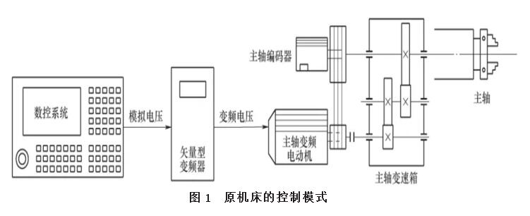
The control method shown in Figure 1 is open-loop control. The numerical control system converts commands of different speeds into analog voltage commands of different sizes to the inverter, and the inverter outputs different frequencies to make the motor rotate with the corresponding speed command.
In order to realize the positioning and stopping of the spindle, an innovative design is carried out from the electrical control, and a general-purpose programmable controller, PG card and relay are added. After the transformation, the control mode of positioning stop is added, as shown in Figure 2.
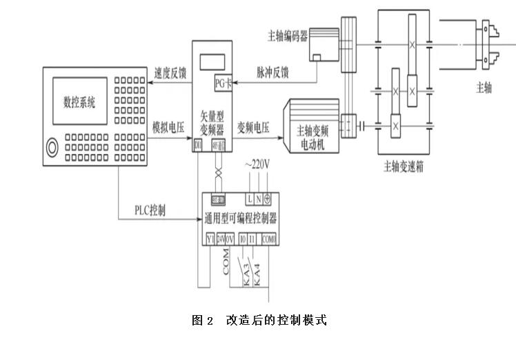
In Figure 2, the numerical control system outputs high and low gear positioning signals (KA3 and KA4 are closed) to the programmable controller. After the internal PLC processing of the controller, each parameter signal is given to the frequency converter, and the frequency converter controls the motor to stop. At the same time, the encoder will feed back the spindle stop position to the inverter, and the PG card will feed back the position to the CNC system to form a closed-loop vector control mode. As an intermediate communication module, the programmable controller sets up a bridge between the inverter and the numerical control system for shifting, positioning and stopping, and changing the internal parameters of the inverter without a lot of PLC programming.
03 Principles of Electrical Control
The electrical principle of increasing the positioning stop of the inverter is shown in Figure 3. The circuit breaker Q F controls the frequency converter and the motor power supply. The spindle speed analog signals SVC and AGND output by the numerical control system are connected to the frequency converter A11 and GND terminals. By changing the frequency of the frequency converter, the spindle motor rotates at different speeds. The PLC program in the numerical control system controls the coils of the relays KA1 and KA2 to turn on to make the spindle forward and reverse. If the inverter fails, the TA and TB terminals will output an alarm. In order to stop the spindle positioning, two relays KA3 and KA4 are added to control the positioning of high and low gears.
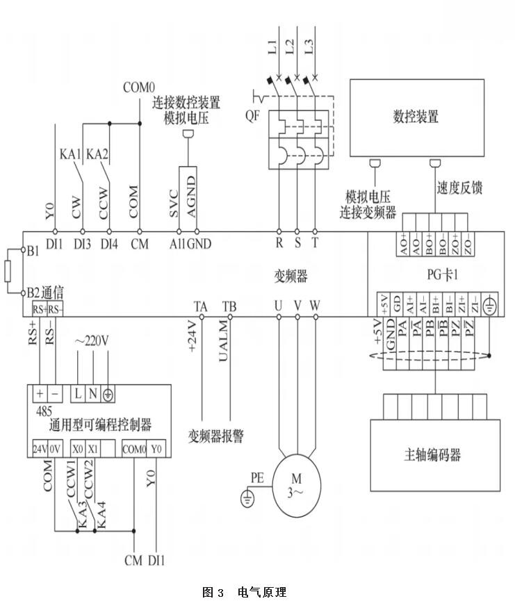
In Figure 3, KA1 and KA2 normally open points respectively control the spindle forward and reverse rotation, KA3 is the gear switching control, and KA4 is the spindle positioning stop control. The control circuit defaults to positioning and stopping during high gear processing. When it is necessary to switch to low gear for positioning, the normally open point of relay KA3 is closed. No matter which gear you are in, you need to execute the positioning stop command M26, the CNC system outputs a signal, and the KA4 normally open point is closed, and the positioning stop cancel command M27 is executed, and KA4 is disconnected.
04 PLC transformation
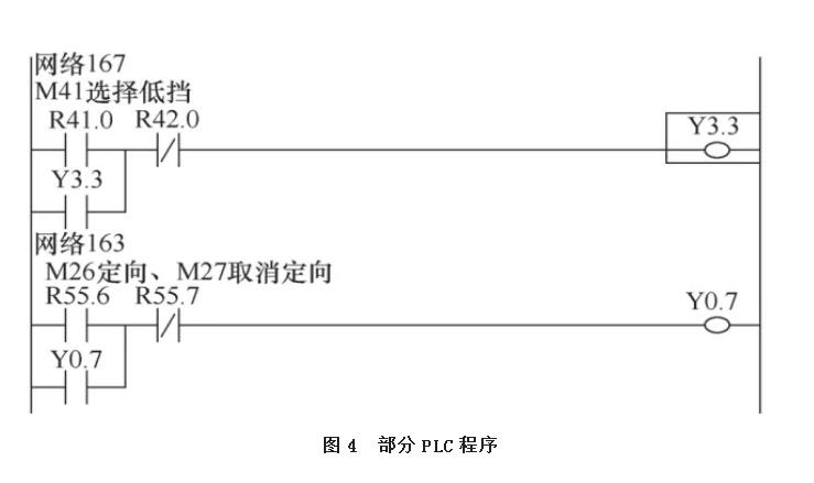
The specific operation is as follows. When the machine tool executes M42 processing in high gear, the M26 positioning stop command is input in the program, the CNC system PLC output, the KA4 normally open point is closed, the programmable controller communicates with the inverter, and the spindle performs positioning stop. When the machine tool executes M41 processing in low gear, the CNC system PLC outputs, the KA3 and KA4 normally open points are closed, the programmable controller communicates with the frequency converter, and the spindle performs positioning and stops. The 980TDc system PLC program intercepting part of the program is shown in Figure 4. Y3.3 controls the KA3 coil and is executed when the low gear is selected; Y0.7 controls the KA4 coil and executes the M26 orientation selection and M27 orientation cancellation.
05 concluding remarks
This control method is suitable for the transformation of the positioning and stopping function of the variable frequency spindle of the lathe. On the basis of meeting the processing requirements, the original machine tool does not need to be eliminated, and no large-scale transformation is required, which can reduce the transformation cost of the enterprise. The transformation of the positioning and accurate stop function of the frequency conversion spindle of the multi-speed CNC lathe not only enables the machine tool to achieve positioning and accurate stop in different gears, but also can be used as a reference for the majority of machining enterprises.