


Tool grinder
The tool grinder has high precision, good rigidity, economical and practical, and is especially suitable for sharpening various small and medium-sized tools, such as reamers, taps, twist drills, reaming drills, various milling cutters, milling cutter heads, and gear sharers. With the corresponding accessories, the outer circle, inner circle and plane can be ground, and samples and molds can also be ground. All kinds of carbide tools can be sharpened with diamond grinding wheel.
Tool grinder is a necessary auxiliary equipment for metal cutting processing, which is used to sharpen various metal cutting tools. Due to the continuous improvement of metal cutting processing technology, metal cutting machine tools are constantly innovated, which requires new cutting tools, and new requirements for tool sharpening are also constantly put forward.
Tool grinder is a grinder specially used for tool manufacturing and tool sharpening.
MQ6025A universal tool grinder is an improved T tool grinder with excellent performance. After it is installed with accessories, it can not only sharpen common tools such as reamer, milling cutter, inclined groove hob, broach, gear shaper, etc. and various special tools, but also can grind outer circle, inner mesh plane and template, etc. The processing range is relatively wide.
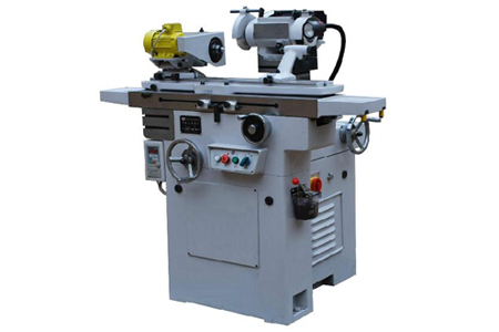
1. Bed
The bed is a box-shaped integral structure casting, with a set of longitudinal V-shaped guide rails and flat guide rails in front of the upper part; and a set of horizontal V-shaped guide rails and flat guide rails at the back. The longitudinal guide rail is equipped with a workbench. The transverse rail is equipped with a transverse carriage, and the left door and rear door of the bed are equipped with electrical components.
2. Workbench
The worktable is divided into two parts: the upper worktable and the lower worktable. The lower worktable is installed on the longitudinal guide rail of the bed, and the guide rail is equipped with cylindrical needle rollers, so that the worktable can move lightly and evenly quickly. There are 4 handwheels for the back and forth movement of the worktable, which is convenient for manipulating the worktable in different positions for grinding.
3. Horizontal carriage
The lateral carriage is mounted on the lateral guide rails of the bed, and there are cylindrical needle rollers between the guide rails. The transverse drive is driven by the hand wheel through the trapezoidal screw and nut. One turn of the handwheel is 3mm, and one small grid is 0.01mm. Since the handwheel is mounted on the same lead screw, it can be operated while standing in front of and behind the machine. A grinding head frame and a lifting mechanism are installed on the horizontal carriage, the hand wheel is shaken, and the grinding head frame is used for lateral feeding.
4. Grinding head and lifting mechanism
The grinding head motor adopts the standard A1-7132 motor. The parts are assembled, and the casing and the grinding tool shell are cast into a whole; the motor stator is changed from internal pressure fitting to external pressure fitting, and a miniature V-belt is used to drive the main shaft of the grinding head to rotate. Grinding wheels can be installed on the cones at both ends of the grinding head spindle for grinding. The speed is 4200 rpm and 5600 rpm in two gears. The grinding head motor can run forward and reverse according to the grinding needs, and is controlled by the steering selection switch of the control panel. The lifting mechanism of the grinding head adopts a cylindrical guide rail, which is guided by an oblique key. There are two types of grinding head lifts: manual and motorized. when manually. Turn the handwheel, reduce the speed through the turbine pair and increase the speed through a pair of spur gears, and make the guide rail rise or fall through the nut and the screw rod. When maneuvering, press the lift button (motorized button on the control panel), the motor starts, decelerates through a tooth difference, connects the screw rod through the joint, and raises or lowers the guide rail through the nut.
Machine tool accessories
1. Left and right center seats: The left and right center seats are mainly used to clamp tools with center holes and tools that need to be clamped with a center shaft.
2. Universal collet: The universal collet is mainly used to clamp end mills, end mills, three-sided disc milling cutters, angle milling cutters, etc., to sharpen the end teeth or conical teeth.
3. Universal tooth drag frame: The function of the universal tooth drag frame is to make the cutter teeth of the tool in the correct position relative to the grinding wheel to grind the required geometric angle.
There are many shapes of tooth trays. It can be made according to actual needs and used for sharpening various knives.
Manipulation and Adjustment
1. Manipulation and adjustment of the workbench
①The choice of the operator’s standing position. When the universal tool grinder is performing internal and external grinding, the operator should stand in front of the machine because the worktable handle is on the right side of the front of the machine, which is convenient for operation and observation. When sharpening the tool, due to the different grinding forms, in order to facilitate the operation and observation, the operator generally stands on the left or right side behind the machine tool table.
②The selection and manipulation method of the joystick. Choose the joystick according to the grinding style. When grinding the inner and outer circles, operate the handwheel,
The table moves slowly and evenly. Sharpen the tool, operate the handwheel, and move the table quickly.
③ Adjustment of the travel distance of the worktable. Since the worktable adopts cylindrical needle roller guides, a little carelessness during operation will cause the stroke to be overdone. In order to control the stroke during grinding, the stopper can be used to limit the position. The method of using the iron block is basically the same as that of the cylindrical grinder.
2. Adjustment of grinding head position
During tool sharpening, the grinding head is rotated 90° clockwise, so that the axis of the main shaft of the grinding head is perpendicular to the axis of the table.
3. The assembly and disassembly of the grinding wheel flange or the extension shaft on the main shaft of the grinding head
① Install the grinding wheel on the flange, and tighten the nut with a special wrench.
② Put the flange together with the grinding wheel on the spindle of the grinding head.
③Insert the locking pin to lock the grinding head spindle.
④ Screw on the hexagon socket head screw and tighten it with a hexagon socket wrench.
⑤ Install the protective cover and pull out the locking pin. The grinding wheel is installed.
When exchanging flanges. The grinding head spindle must be locked; then remove the flange socket head cap screws. Screw on the dismounting wrench and push the flange out of the grinding head spindle.
tool grinder design background
The tool grinder is generally used to process the taper milling cutter in the indexing fixture, and the elongated and special-shaped cutter needs to be processed in the two centers. The grinding machine table can not move the angle longitudinally. After the improvement of the tooling, the two centers can move at any angle in the longitudinal direction, which is convenient for the processing of the taper tool and the workpiece.
Process points
1. Since the tool grinder is designed to have no vertical angle of the worktable, a bending plate fixing plate is installed on the mobile worktable of the machine tool to fix the rotatable angle bending plate to realize the angle processing of the workpiece.
2. T-slots are milled on the working face of the angled bending plate, and the front and rear center seats are installed. 90° vertical boring, locked on the vertical surface of the fixed plate by the positioning shaft nut.
3. Since the tooling is installed on the fixed plate, the angle can be moved longitudinally, and the taper tool can be processed in the two centers. The entire tooling can also be adjusted by the two T-slot bolts of the fixed plate.
4. The corner bending plate and the bending plate fixing plate are processed with cast iron plate, and other fasteners are processed with 40Cr quenching and tempering treatment. The front and rear top seats should be processed to be lightweight, which is convenient for up and down adjustment.
Principle features
The corner bending plate 4 is machined with T-shaped grooves, and the front and rear center seats 2 are installed, which are positioned and locked by the T-shaped groove bolts 3 and the positioning keys 11. The bending plate fixing plate 6 is fixed to the machine tool by two T-shaped groove bolts 7. The table top and the side are installed with the bending plate positioning shaft 5, and the turning angle bending plate 4 is installed in the bending plate positioning shaft 5, which can be rotated to adjust the angle, and is locked with the tightening nut 9. Part 10 is a workpiece support plate, which is fixed on the vertical surface of the corner bending plate and used to support the machining of the tooth surface of the tool.
Effect
It solves the difficulty of machining the taper workpiece in the two centers, and adds a new tool for the finishing of the tool. The tooling is simple and light, and the adjustment and loading and unloading are convenient, which expands the processing range of the machine tool.