


Machining shaft workpieces is the most basic function of CNC lathes, and ensuring that the processing quality of shaft workpieces meets the requirements is an important standard for testing the performance of CNC lathes.So in addition to the general operating procedures, for the characteristics of shaft workpieces, what problems should we pay attention to in the actual processing process?

In view of this problem, it can be summarized as the five core elements of “clamping, tool, programming, measurement, and safety”.
| Element | Function | Description |
| 1. Clamping: The foundation for ensuring coaxiality and rigidity | 1. Benchmark Unification and Selection: | Try to use the centers at both ends as the positioning benchmark (i.e., “double centering”), which is the best method to ensure the coaxiality of each section of a multi-step shaft.
CNC lathes can be used in conjunction with a power rotating center. If a chuck is required for clamping, choose a section with a larger diameter, longer length, and smoother surface as the clamping benchmark. |
| 2. Clamping Method and Alignment: | Rough machining: A chuck can be used for direct clamping (with sufficient allowance), but the clamping length should not be too short to ensure rigidity. Finish machining or secondary clamping: A soft jaw or spring chuck that has been machined must be used. Soft jaw machining: Before installing the workpiece, lightly machine the inner circle or end face of the chuck’s soft jaw (the machining diameter should be slightly smaller than the diameter of the workpiece to be clamped) to make it concentric with the spindle. This is a key step to eliminate the inherent errors of the three-jaw chuck and ensure the coaxiality of finish machining. When using a tailstock center, the tightening should be appropriate. Too loose can lead to vibration and the risk of the workpiece falling off; too tight can cause the workpiece to bend, especially for slender shafts, and may burn out the center. |
|
| 3. Special Treatment for Slender Shafts: | A follower rest or steady rest must be used to increase rigidity and counteract the bending deformation and vibration caused by radial cutting forces. The arc surface of the follower rest’s support claws should be lapped to fit the workpiece’s outer circle well. When adjusting the steady rest, it must be done while the workpiece is rotating to ensure that the three support claws make uniform contact. |
|
| 2. Tool: Ensuring Cutting Stability and Surface Quality | 1. Tool Selection and Grinding: | Select the appropriate tool insert material and chipbreaker type based on the workpiece material (steel, aluminum, stainless steel). For rough turning, choose a tool with high strength and good chip breaking; for finish turning, select a sharp and wear-resistant tool. The selection of the tool tip radius should be reasonable: A large radius is beneficial for improving surface finish and tool tip strength, but may cause vibration; a small radius is suitable for finish turning and root clearing. Ensure that the tool tip height is strictly aligned with the spindle center height; any deviation will affect the actual cutting angle and diameter size. |
| 2. Tool Tip Radius Compensation (G41/G42): | Tool compensation must be enabled in the program for finish machining. Otherwise, dimensional errors will occur when machining tapers, arcs, or end faces. When setting the tool, the tool tip radius value and tool tip position number (T value) must be correctly entered into the system; these are the core parameters for accurate compensation. |
|
| 3. Programming and Process: Optimizing Efficiency and Precision | 1. Process Path Planning: | Follow the principle of “roughing before finishing, near before far.” First, remove a large amount of material, then refine the dimensions; start with the part closest to the chuck to increase the rigidity of the far end. Plan the tool path reasonably to reduce idle travel and improve efficiency. For shafts that require heat treatment, appropriate machining allowances (usually 0.3-1.0 mm per side) must be left for subsequent grinding or semi-finish and finish turning. |
| 2. Cutting Parameter Optimization: | Rough machining: Within the limits of the machine and tool, use large cutting depths, large feed rates, and medium-low spindle speeds to improve efficiency. Finish machining: Use small cutting depths (0.1-0.5 mm), small feed rates (0.05-0.2 mm/rev), and high spindle speeds to achieve high surface quality. Use constant surface speed cutting (G96), especially when machining stepped shafts with large diameter variations, to ensure constant cutting speed from large to small diameters, consistent surface quality, and extended tool life. |
|
| 3. Fixed Cycle Application: | Be proficient in using G71 (external rough turning cycle), G72 (face rough turning cycle), G70 (finish turning cycle), G75 (grooving cycle), G76 (threading compound cycle), etc. They simplify programming, improve efficiency, and are optimized by the system for more stable machining. | |
| 4. Measurement and Quality Control: A Continuous Line of Defense | 1. First Piece Inspection and In-Process Sampling: | After the program is debugged, the first piece must be measured for all dimensions while the machine is stopped to confirm accuracy before starting batch production. During machining, periodically sample key dimensions (such as bearing seats, mating shaft necks) to monitor tool wear and make timely tool compensation adjustments. |
| 2. Proper Use of Measuring Tools: | Use a micrometer for outside diameters, a vernier caliper or depth gauge for lengths, and a ring gauge for threads. Geometric tolerances (such as coaxiality, circular runout) should be measured using a dial indicator on a deflection gauge or V-block. Before measuring, clean the workpiece and measuring tools, and wait for the workpiece to cool to room temperature to avoid errors due to thermal expansion and contraction. |
|
| 3. Online Monitoring: | Observe the shape, color, and sound of the chips during machining. Abnormal chips, sharp noises, or vibrations may indicate tool wear, chipping, or unreasonable cutting parameters. | |
| 5. Safety and Details | 1. Collision Prevention: | Simulate the program run, especially for the first time or after modifications. Check if the tool path interferes with the workpiece, fixture, or tailstock. Confirm the accuracy of tool setting data to avoid collisions caused by input errors. |
| 2. Chip Breaking and Chip Removal: | Long, coiled chips are a significant safety hazard, potentially scratching the workpiece, wrapping around the tool, or even causing injury. Ensure that the tool has a good chip breaker geometry, or set reasonable chip breaking points in the program. Regularly clean up accumulated chips inside the machine. |
|
| 3. Secure Clamping of Workpieces and Tools: | After each clamping, confirm that the workpiece and tool are securely fastened. Before starting the machine, double-check that the tailstock and tool holder are locked. |
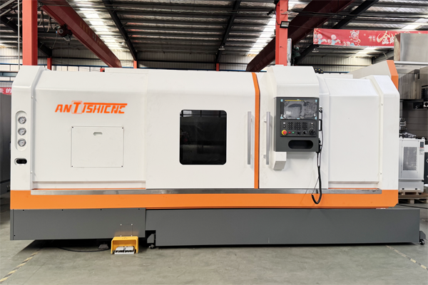
Shanghai ANTISHICNC is a professional manufacturer of CNC lathes. We have rich production and processing experience. We can recommend the most suitable lathe for your products and give suitable suggestions for use. We can provide you with professional technical support. We mainly have CNC lathes, ordinary lathes, vertical lathes, etc. If you have CNC lathe production needs, please contact Shanghai ANTISHICNC, company email:contact@antsmachine.com
Keywords: CNC lathe, lathe processing, lathe clamping, lathe operation