


Take the shaft sleeve parts as an example to illustrate the basic process of CNC lathe processing technology.
(1) Part process analysis. Judging from the process drawing, the parts that need to be processed include holes, internal threads, internal grooves, external circles, external grooves, steps and arcs. The structural shape is relatively complex, but the dimensional accuracy is not high. Attention should be paid to the selection of tools during processing. The holes and external circles have been rough-turned in the previous process.
(2) Determine the CNC lathe clamping plan. Because the total length of the part has been determined in the previous process, the key to clamping this process is positioning. Pre-turn out the φ150 x25 step, and use the three-jaw chuck to clamp the φ150 for turning.
(3) Determine the CNC lathe processing sequence and feed route. Because the shape of the part is complex, multiple turning tools must be used to complete the turning process. According to the specific requirements of the parts and the principle of determining the cutting feed route, the processing sequence and feed route of the sleeve parts are determined as follows:
① Fine turning ф150 x25;
② Rough turning the outer shape and inner hole (M80 x2 thread bottom diameter is φ77.4mm), leaving a margin of 0.4;
③ Fine turning steps φ130, φ120, φ110 and φ100;
④ Fine turning φ100 grooves and tapers;
⑤ Fine turning arc surfaces R25 and R20;
⑥ Fine turning holes φ55, ф77.8;
⑦ Cutting inner grooves φ82 x5;
⑧ Turning inner threads M80 x2.
(4) Select CNC lathe tools and cutting parameters. Select tools and cutting parameters according to the specific requirements of the processing and the surface shape of each process. All the selected tools are carbide machine clamps and welding turning tools.
The workpiece coordinate system is selected at the center of the M80x2 end face, and the tool types are as follows:
Tool No. 1: 90° fine turning tool;
Tool No. 2: rough turning tool;
Tool No. 3: boring turning tool;
Tool No. 4: cutting tool;
Tool No. 5: threading tool;
Tool No. 6: fine boring tool;
Tool No. 7: internal groove tool;
Tool No. 8: internal thread tool.
The tools and cutting parameters used in each process are shown in the following table.
| Process | Cutting amount selection | ||
| Knives | Spindle speed (r/min) |
Feed rate (mm/r) |
|
| Finish turning tool φ150×25 | 90° Machine Clamp Turning Tool | 800 | 0.10 (The last cutting depth should be greater than 0.5mm) |
| (1) Rough turning of the shape | 90° machine clamp rough turning tool | 400 | 0.15 |
| (2) Rough turning of inner holes | Carbide welding turning tool | 400 | 0.10 |
| Finishing steps φ130, φ120, φ110 and φ100 | 90° machine clamped fine turning tool | 800 | 0.10 |
| Finish turning φ100 groove and taper | Carbide welding cutting tool | 400 | 0.10 |
| Finish turning of arc surface R25 and R20 | Carbide welding thread turning tool (tip radius R is 0.4mm) | 800 | 0.10 |
| Finishing hole φ55, φ77.8 | Carbide welding blind hole turning tool | 400 | 0.08 |
| Cut inner groove φ82×5 | Carbide welding inner groove cutter | 400 | 0.08 |
| Internal thread M80×2 | Carbide welding thread turning tool (tip radius R is 0.4mm) | 800 | 2 |
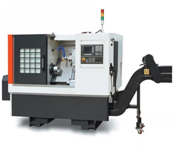
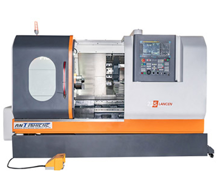
CNC Lathe recommendation:
|
|